

Load Combinations To Calculate Your Design Loads
#12th episode of the Structural Loads Series

Happy Wednesday, 👋👋
Timber beams, steel columns and reinforced concrete slabs are all designed and verified with design loads calculated from load combinations.
Load combinations combine different loads like snow, wind, dead, seismic and live load to represent a “real scenario”. A real scenario is for example the resulting force for a heavy wind storm. By setting up all possible load combinations we will find the worst-case scenario for a structural member which is in many cases the biggest load.
To put it in context, in load combinations we combine the characteristic loads we calculated in the last weeks (dead, live, snow, wind, impact load, earth pressure and imperfections). To account for material failure and to account for extra safety, we also apply safety factor to the characteristic loads.


I spent most of my weekend updating the blog post about load combinations, which is the basis of this newsletter. The blog post became sooo long that we’ll split up this article in part 1 (today) and part 2 (next week). Otherwise, it would be too long.
So, in today’s article, you’ll learn how to set up ULS, accidental and seismic load combinations according to EN 1990, so you know with what design load you need to verify your structure.
Next week, we’ll look at SLS characteristic, quasi-permanent and frequent load combinations.
13 Windows Shortcuts Everyone Should Know About
Scroll down, if you are only interested in load combinations.
As engineers, our “products” are drawings, calculation reports and 3D models which we create on our computers from which buildings and structures are built.
The more of those products we create in a certain time, the more we get paid or the less we have to work.
So it’s crucial to increase the productivity of our digital workflows to save time, document better and stay competitive in this fast-paced world we live in.
Today, I’ll share 13 Windows 🪟 shortcuts that save me minutes at work every day.
Now, back to load combinations…
Load Combinations According To Eurocode (Part 1)
As always, we’ll use an example structure to explain how to apply the design loads that we calculate in load combinations. This time, it’s a carport with timber beams and columns and wind bracing.

Before we jump into the load combinations, let’s clarify what ULS and SLS is and what it means.
ULS = Ultimate limit state
Structural members like columns, beams and slabs are designed for bending, shear, buckling, etc. in ULS.
SLS = Service limit state
Structural members like columns, beams and slabs are designed for deflection, vibrations and cracking in SLS.
Now, let’s check out how we set up these load combinations…
#1 ULS Load Combinations
Due to ULS load combinations, structural members are designed for bending, shear, buckling, etc. EN 1990 6.4.3.2 calls ULS load combinations “Combinations of actions for persistent or transient design situations”.
The formula of ULS load combinations is (EN 1990 (6.10)):

With,
γG = Partial factor of the dead load
Gk = Dead load
γQ.1 = Partial factor of the leading variable action/load like live, snow or wind load
Qk.1 = Leading variable action
γQ.i = Partial factor of the accompanying actions/loads like live, snow or wind load
ψ0.i = Psi factor of the accompanying actions/loads
Qk.i = Accompanying variable action
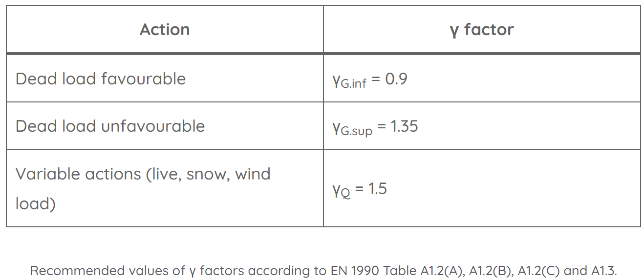
Partial factors
The partial factors are found in EN 1990 Table A1.2(A), A1.2(B), A1.2(C) and A1.3. Note that these factors might be defined differently in your National Annex.
ψ0 factors
We find the ψ factors in EN 1990 Table A1.1. Please be aware that every country might define these factors differently in its National Annex.

ULS load combinations applied to example structure
According to Eurocode EN 1990 (6.10) in our example the load combinations can be written as:
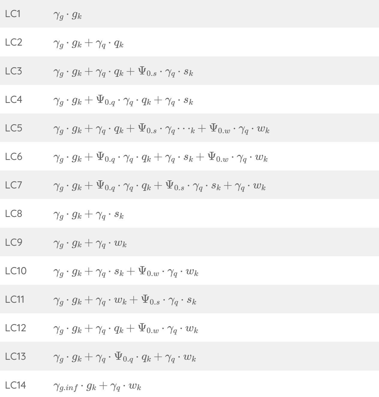
Putting in the values of the characteristic loads, psi and gamma factors, we’ll get..

Don’t worry, you do not have to do this manually every time because luckily most FE programs do that for us.
But if we were to dimension a timber beam for bending now manually we would use the biggest value of the load combinations which is 4.0 kN/m2 (LC3) and transform it first in a line load (kN/m).
Assuming that the beams have a spacing of 0.8m, we get the following line load:

That line load can now be applied to the static system of the secondary beams.

#2 Accidental Load Combinations
According to EN 1990 1.5.3.5 an accidental action is defined as:
Action, usually of short duration but of significant magnitude, that is unlikely to occur on a given structure during the design working life.
Example of accidental design situations are a fire, an explosion, impact loads from vehicles or the consequences of localized failure.
The formula of accidental combinations is (EN 1990 (6.11b)):

With,
Gk = Dead load
Ad = Accidental action/load like e.g. impact load from vehicle
Qk.1 = Leading variable action
ψ1.i or ψ2.i = Psi factors of the variable actions/loads
Qk.i = Accompanying variable actions
ψ1 and ψ2 factors

Accidental load combinations applied to example structure
Let’s say the accidental action is an impact load from a car that crashes into one of the columns of the carport.

According to our article about impact loads from vehicles the accidental action Ad is defined as:

Now, let’s assume that the characteristic vertical loads on the column are:


According to Eurocode EN 1990 (6.11b) in our example the load combinations can be written as:

Now, you can go ahead and design the timber column for the horizontal and vertical design load.
#3 Seismic Load Combinations
Seismic actions and load combinations are the result of earthquakes. In many parts of the world this is the leading horizontal design load acting on a building and in other parts the seismic load is much smaller than the horizontal wind load.
The formula of accidental combinations is (EN 1990 (6.12b)):

With,
Gk = Dead load
AEd = Design value of seismic action
Qk.i = Variable actions
ψ2.i = Psi factors of the variable actions/loads
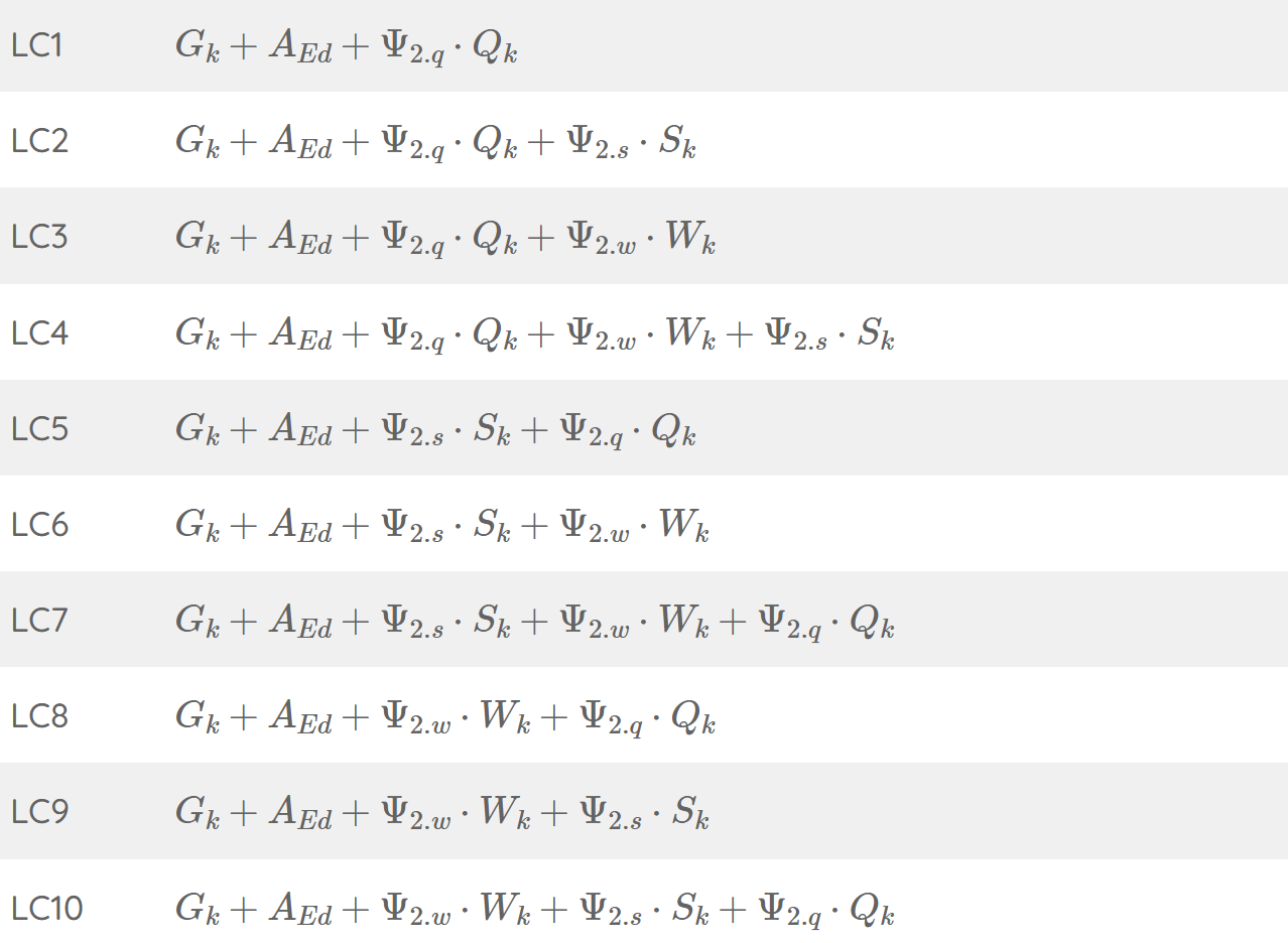
Seismic load combinations applied to example structure
According to Eurocode EN 1990 (6.12b) in our example the load combinations can be written as:
How you calculate AEd is a topic for another article.
Final Words
Well, final words don’t really fit here, because we’ll continue with part 2 next week.
Next Wednesday, we’ll look at:
SLS characteristic load combinations
SLS quasi-permanent load combinations and
SLS frequent load combinations
If you missed episode #1 - #11 of this series, then you can find all previous posts → here ←.
Enjoy the rest of the week and see you next Wednesday. 🙋♂️🙋♂️
Cheers,
Laurin. 😎😎
Hi Mate, I'm a big fan of you. Could you please present simple calculation examples for each expectation of structural engineering? I know it's hard work but worth learning a lot of things from an expert person like you. Thanks
I think in the ψ0 table the numbers are mixed up for >1000 (0,7) and <1000 (0,5)