

Imperfection Loads: How You Calculate And Apply Them In Your Design
Episode #10 of the Structural Loads Series

Hello friends, ✌️✌️
Deviation of the geometry of a structure such as slightly inclined columns/walls or imperfections of the cross-section in the execution phase happen. No structure is 100% as we calculate it.
To account for these deviations of the structure, we use imperfection loads in our structural calculations.
We calculate the imperfection load according to DS/EN 1992-1-1. And we take them into account in ULS and ALS, but not in serviceability limit states (SLS).
Loads from imperfections are calculated for each floor and applied as a horizontal load on the floor diaphragms.

So, in today’s article, you’ll learn how to calculate the imperfection load according to EN 1992-1-1, so you know how to include it in your designs. It’s a 2-step process. We’ll first calculate the inclination of the vertical elements θi and then the vertical design load in order to calculate the imperfection load.
Finally, we’ll show how to apply imperfection loads on floor diaphragms and shear walls in ULS design with the wind load.
Why I Started Structural Basics
Scroll down, if you are only interested in the imperfection load calc.
Creating content on Structural Basics has definitely uplifted my personal and professional life.
On the one hand, I learned new and improved existing skill sets and on the other hand, content creation excites me.
I broke it down into 6 reasons why I created Structural Basics and I can only encourage you to also start creating content. There is still a big lack of content in our industry compared to others.
Reason #1: The Need For Step-By-Step Structural Design Guides:
An architecture friend of mine asked me how she can learn how to design timber flat roof beams for a small summer house. I was sure I can simply google “timber flat roof beam”, send her the best guide I can find and add some additional information like where to find certain properties, codes and what software to use.
I was shocked how little structural design content I could find online, and knew that I have to change that.
Reason #2: Creating = Deepens Knowledge
Creating content around a topic you are knowledgeable about deepens your own knowledge a lot! By writing it down, I often find myself that I don’t remember any more how exactly things worked. Then I go back to study it again.
Reason #3: You’ll Learn New Skill Sets
When diving into the world of content creation, you have to learn a lot of new things. For me, that was:
Homepage design
Keyword research
Thumbnail design
SEO optimization
I definitely improved my writing skills. It became more engaging and my writing got easier to follow. I am not a big fan of long sentences with many technical words which you have to read twice before you understand it.
Reason #4: Creating Content Is Fun
Above all, it’s been a lot of fun to start Structural Basics.
Reason #5: Connecting With People
It’s inspiring to get good feedback from people you could help with your content. I really enjoy receiving loads of e-mails and connecting with you, readers.
Reason #6: Content = Digital Asset
A blog, Instagram page or YouTube channel is like a digital asset and portfolio where you can present to clients or employers what you know. If you build an audience, and you produce quality content, you’ll have it easier finding a job or even companies will come to you.
Now, back to the imperfection load calculation…
The 4 Steps To Calculating And Applying The Imperfection Load In Your Structural Design
As always, we’ll use an example structure to explain the calculation steps. This time, it’s a 1-storey concrete building with a flat roof slab and walls taking up the vertical and horizontal loads.

The imperfection load is calculated with EN 1992-1-1 (5.1):

With,
Nd.i = Vertical design load on floor i in the given load combination; see next figure
θi = Inclination of the vertical elements; see next figure (calculated in the next section)
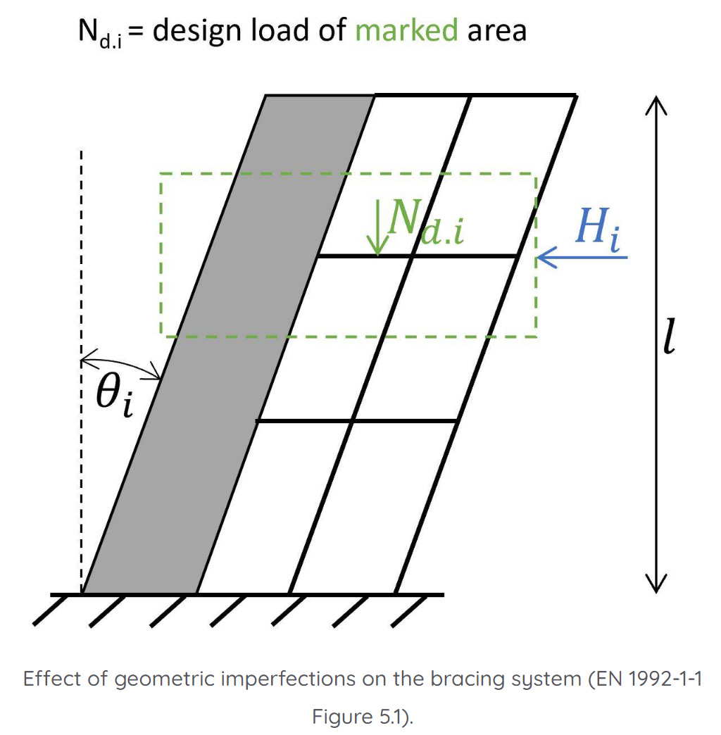
Now, let’s run through the #4 steps to calculate the imperfection load of the roof diaphragm.
Step 1: Inclination of the vertical elements θi
The inclination θi, is given by (EN 1992-1-1 (5.1)):

With,
θ0 = Basic value. EN 1992-1-1 (5.1) recommends a value of 1/200. This means that this value could be defined differently in the National Annex. We’ll use θ0 = 1/200 for our example
αh = 2l; 2/3 ≤ αh ≤ 1. For l = 4m as the height of the structure, we get 2/√l = 1.0 > 2/3 → αh = 1.0
αm = √(0.5⋅(1+1/m)). For m = 5 as the number of vertical members (number of walls in our case) contributing to the horizontal force on the bracing system, we get αm = √(0.5⋅(1+1/m)) = 0.77.
With these values, the inclination is calculated as:

Now, we need to calculate the vertical load on the floor/roof…
Step 2: Vertical design load on the floor/roof
I usually create a table in Excel with all the quantities like area of floors and walls and length of columns and beams.
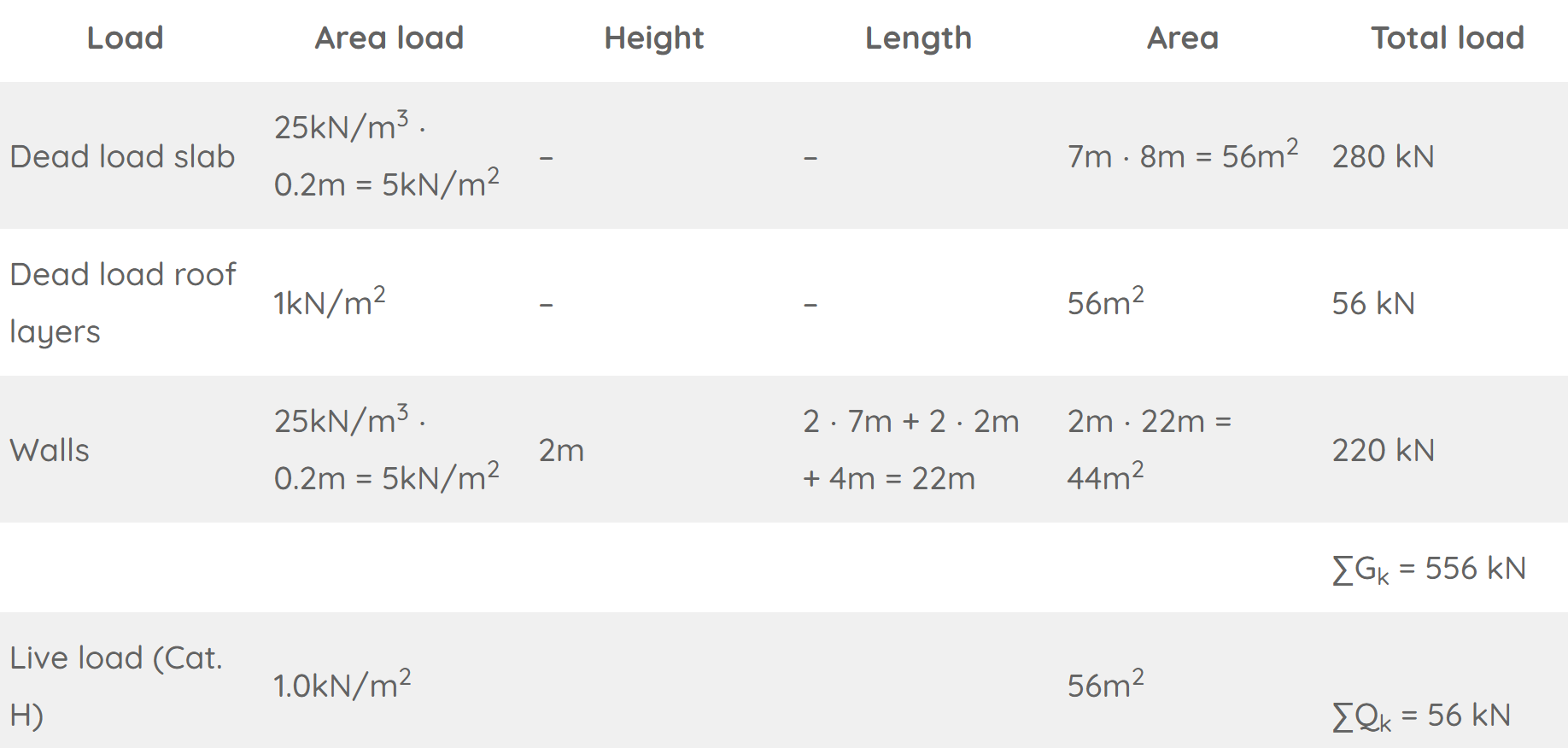
Note, that we only use half of the weight of the walls, because the other half is considered in the imperfection load of the floor below/raft.
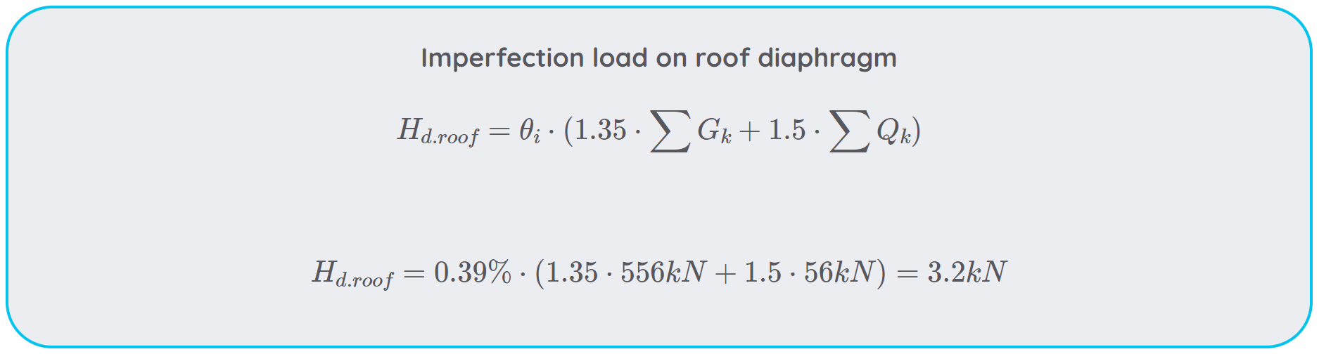
Step 3: Calculation of the imperfection load on the roof floor
We can finally calculate the ULS imperfection load on the roof floor:

But the imperfection load is always used with other loads, like the wind or seismic loads. Let’s have a look at how we combine the loads and how to apply the total horizontal loads on the shear walls…
Step 4: Applying the imperfection load on floor diaphragms and stabilizing elements
The ULS imperfection load is used in the stability analysis of the structure due to wind. It’s added to the horizontal wind loads on the roof diaphragm.
When the stability of the structure is verified due to seismic loads, an accidental imperfection load need to be calculated. So basically without the partial safety factor for the live load.
Example
Let’s say:
the design wind load of area D is calculated as 1.0 kN/m2 and of area E as 0.65 kN/m2.
the wind direction is perpendicular to the facade of width 8m.
half of the wind load is taken by the roof diaphragm and half is transferred to the raft.
These assumptions lead to a wind line load of area D of 1.0 kN/m2 ⋅ 4m/2 = 2 kN/m and area E of 0.65 kN/m2 ⋅ 4m/2 = 1.3 kN/m. When we design and verify the diaphragm, we would also need to add the imperfection load and distribute it as a line load. But I want to show you how to add the imperfection load to the stability analysis.
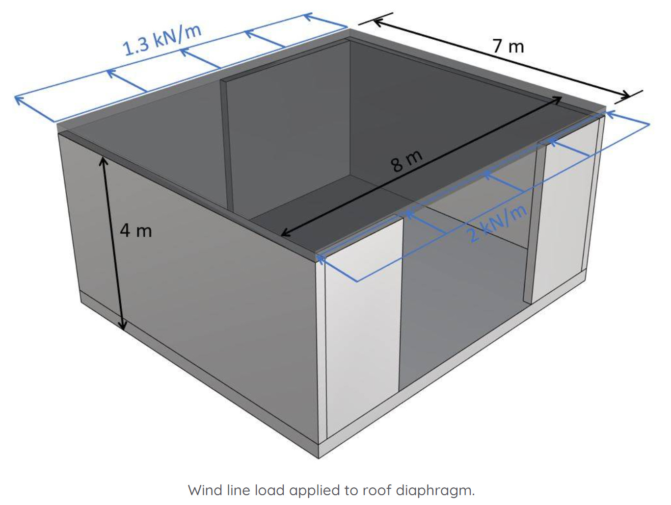
When verifying the stability, the line loads travel to the shear walls, which are placed in the same direction as the load. For this type of building, we can assume that half of the load is taken by the left wall and half by the right wall.
The total point load due to wind on the walls/diaphragm is calculated as:

We add the imperfection load to this wind load. This way, the imperfection load is included in the stability analysis of the shear walls.


Final Words
The shear walls can now be designed and verified for the horizontal design load of 14.8 kN, which includes the imperfection load.
Next week, we’ll check out the last type of structural load. ✌️✌️
If you missed episode #1 - #9 of this series, then you can find all previous posts → here ←.
Enjoy the rest of the week and see you next Wednesday. 🙋♂️🙋♂️
Cheers,
Laurin. 😎😎