

Wind Loads On Pitched Roofs
Episode #7 of the Structural Loads Series

Happy Wednesday everyone, 🙋♂️🙋♂️
This is the last post about wind loads before we continue with the next type of load. There are of course other geometries and structures that we are not covering in this series such as arches, domes, freestanding walls, canopies, bridges, the list goes on.
However, these are more special cases. The wind load on walls, flat and pitched roofs are enough in 90% of our structural designs. I want to bring you guys up to speed with the most essential things in structural engineering before diving deeper into the nerdy and more complex topics.
Some of you reached out and asked me to cover some of these more special cases. I hear you and I appreciate every feedback, comment and suggestion from you guys. I will get into these topics in the future when I have more time again and when we are done with these basic structural engineering series.
Today, we’ll show how to calculate the wind loads on pitched roofs.
In the last 2 weeks we learned that the wind loads on walls are included in the stability analysis of the building, while the wind loads on flat roofs are taken into account when designing horizontal elements such as beams, slabs, etc.
The wind loads on pitched roofs need to be considered in both, the verification of stabilizing and horizontal elements. Read on to find out why.
Let’s get into it. 🚀🚀
Step-By-Step Process Of Calculating The Wind Load On Pitched Roofs
In order to calculate the wind load or wind pressure on pitched roofs, we are going to do the following steps:
Calculate the peak velocity pressure qp
Define the outer geometry of the building (width, height, length)
Calculate the width of the wind areas
Find the external pressure coefficients from Eurocode
Calculate the wind pressures/loads on the flat roof
Example Building
We’ll use the following timber roof to show all the steps of calculating the wind load on the pitched roof.

#1 Peak Velocity Pressure
The peak velocity pressure of the building located in Copenhagen, Denmark is calculated as:
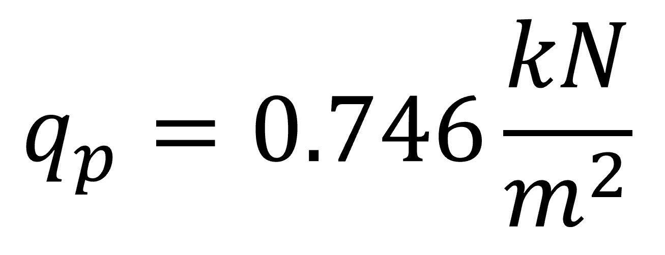
We showed, step-by-step, how to calculate the peak velocity pressure in → this article ←. Or check out our YouTube video.
#2 Define the outer geometry of the building (width, height, length)
The building has the following dimensions:


Based on the geometry, we can now calculate the wind load areas in step #3. ⬇️⬇️
Communication in engineering is equally important as technical knowledge
From now on, I will be sharing more of my thoughts and experiences in the weekly newsletters in between the nerdy structural content. Feel free to scroll down to step #3 if you're only here for the structural design content.
I started documenting what’s on my mind here on Substack as Notes.
Every morning I sit 30 mins. in the train going to work. Part of this time I’ll be using to be creative and share insights from my day-to-day job as a structural engineer.
Today we’ll start with a few examples of bad communication in building projects that I have experienced.
Please let me know if you’re interested in these small snippets.
Everyone who knows me, knows how much I emphasize the importance of communication in our industry. I think communication skills are equally important as technical skills to achieve a successful project.
Click on the note to see the full text. 👇👇
Next time, my thoughts on how to improve communication.
#3 Calculation Of The Width Of The Wind Areas
The wind load on walls is split up in 5 different areas according to EN 1991-1-4 Figure 7.8.
We will be talking about wind from front and side in this article. The following picture emphasizes what we mean by front and side.

Wind from front (wind direction towards the inclination of the rafters)
According to EN 11991-1-4 Figure 7.8, the width and length of the building (parameter d) for wind in from front are defined as following:

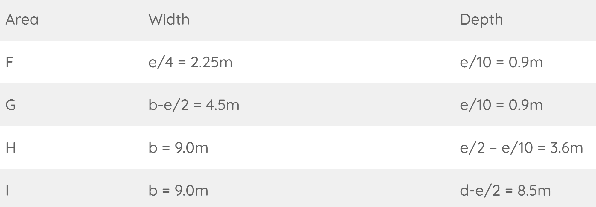
From those dimensions we can define e which determines the dimensions of areas F, G, H, I and J according to EN 1991-1-4 Figure 7.6.

From e we get the dimensions of the areas according to EN 1991-1-4:2005 Figure 7.8.

This leads to the following wind load areas (2d view).
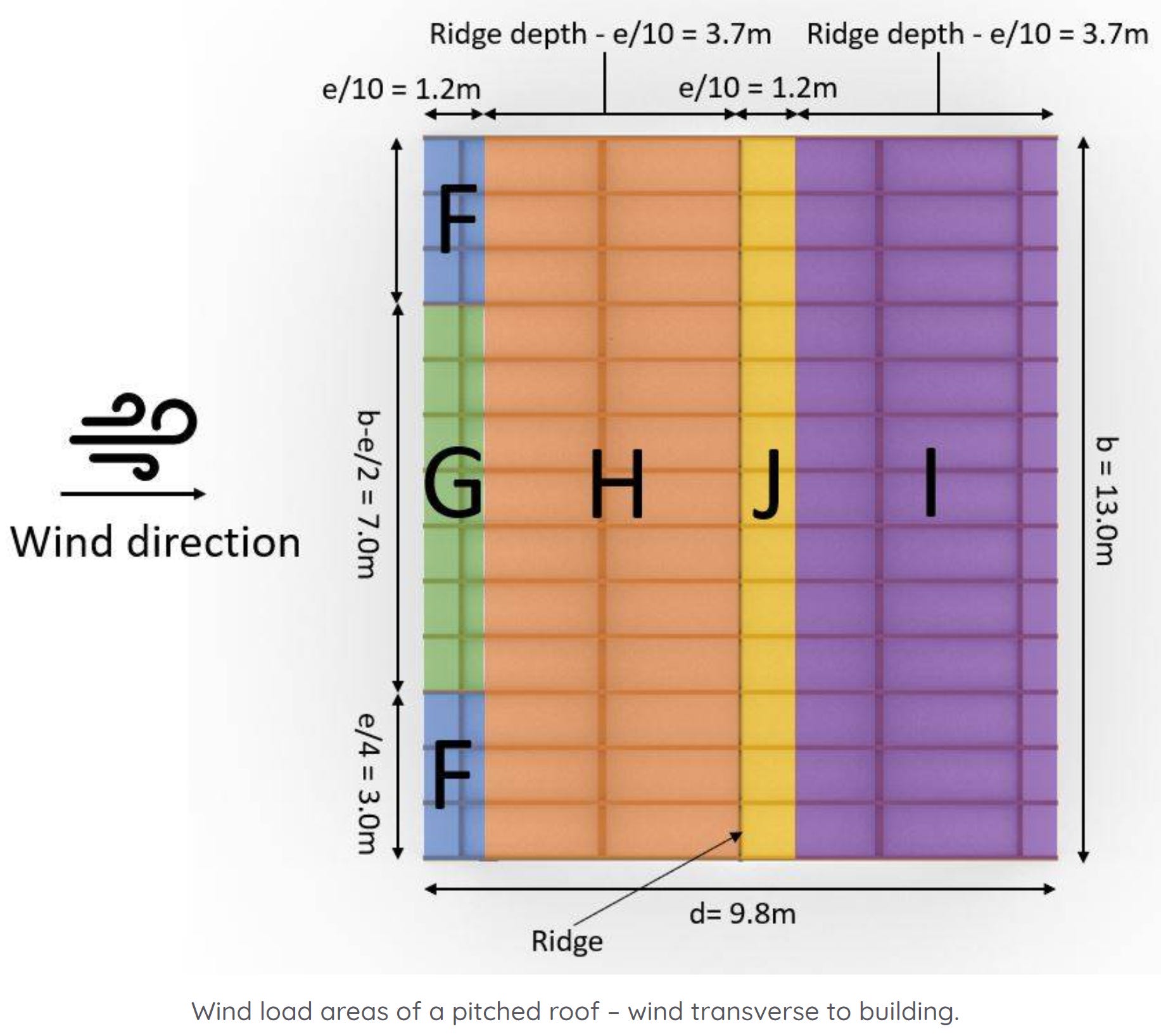
To understand it better, a 3d representation helps.

Wind from side (wind direction towards the gables)
In the scenario that wind comes from the side, we have to define the area widths again. We have to redefine the geometry parameters.

From those dimensions we can define e according to EN 1991-1-4 Figure 7.8.

From e we get the dimensions of the areas according to EN 1991-1-4:2005 Figure 7.8.
Let’s visualize that.

#4 Find The External Pressure Coefficients From Eurocode
First, here’s the formula to calculate the characteristic wind load (it’s the same as for wind loads on walls and flat roofs):

Where,

So, here in #4, we’ll find the values of cpe for the different wind load areas.
EN 1991-1-4 Table 7.1 gives recommendations for cpe. This means that you have to double-check with your national annex because those values might be defined differently there.
Pressure coefficients for wind from front
Tables 7.3a and 7.3b give values for 4 different areas F, G, H and I of our roof. Those areas depend on where the wind comes from and the shape of the roof.
Eurocode differentiates between mono- and duo pitched roofs.


The external pressure coefficients for duopitch roofs with wind from front (direction angle Θ) can be taken from EN 1991-1-4:2005 Table 7.4a.
For a roof slope angle of 29° ≈ 30°, we get the following pressure coefficients

Don’t be confused by the + and – of the coefficients of Area I. EN 1991-1-4:2005 Table 7.4a Note 1 says that due to rapid change wind, both positive and negative values are given. Therefore, 4 cases need to be considered in total – the smallest and largest coefficients of areas F, G and H with the smallest or largest coefficients of areas I and J.
Pressure coefficients for wind from side (/on gables)
The external pressure coefficients for duo pitched roofs with the wind direction of Θ = 90° and a roof slope angle of 29° ≈ 30° can be taken from EN 1991-1-4:2005 Table 7.4b.

Now, let’s calculate the wind loads. 🌬️🌬️
#5 Calculation Of The Wind Load On The Pitched Roof
Based on the pressure coefficients, we found in #4 and the peak velocity pressure qp we can now calculate the wind load of the 5 wind areas.
Wind from front (wind on inclined rafters)

Let’s apply the wind loads with the cpe.10 coefficient (for 10 m2) on the rafter roof.

Wind from side (wind on gables)

Those wind area loads we can also visualize in 3D.

Conclusion
For a building with a duo pitched roof with the height of 6.0 m in a suburban area in Copenhagen, Denmark, the wind load on the roof is calculated for 5 different areas and 2 wind directions.
As said in the introduction, the direction of the wind load is perpendicular to the surface of the roof. This means that the load has a horizontal and a vertical component.
Vertical component is applied on horizontal and vertical elements like beams, slabs, walls and columns
Horizontal component is applied to the stabilizing system of the building. This can be wind braces, shear walls and diaphragms.
To learn how to calculate the wind load on arches, check out → this article ←.
Next week, we’ll check out how to calculate the wind load on pitched roofs.
If you missed episode #1 - #6 of this new series, then you can find all previous posts → here ←.
Have a great rest of the week.
Until next Wednesday. 🙋♂️🙋♂️
Cheers,
Laurin. 😎😎
Enjoy the newsletter? Please forward to a friend you think could like our structural engineering content. It only takes 14 seconds. Making this one took a few hours. Just forward this link: https://www.structuralbasics.com/newsletter/