The Wind Load / Peak Velocity Pressure
Episode #4 of the Structural Loads Series
Happy Wednesday, 🙋♂️🙋♂️
The last 2 weeks, we covered the dead and live load. Today and the next 2 weeks, we’ll check out how to calculate the wind load. We start by calculating the peak velocity pressure in this episode.
This is 90% of the work to calculate the wind load. Next week, we’ll learn how to calculate the wind load on walls and the week after on roofs.
The Wind Load
The wind load is the resulting force of the wind that blows on a building or structure. The wind load acts always perpendicular to the element surface/plane. This means that for inclined roofs, flat roofs and walls the wind load is always applied in an angle of 90° to the elements.
The wind load always has to be calculated as a vertical load on roofs and other horizontal elements, and as a lateral/horizontal load on walls and facades.
This separation is important, because a building/structures needs to have a vertical and lateral load bearing system. University mainly focuses on the vertical load bearing systems and often doesn’t cover bracing systems like diaphragms, shear walls and tension rods. That’s something we’ll cover in a future episode.
YouTube Video
If you prefer video, you can also check out this YouTube video that I made.
Process of Peak Velocity Pressure Calculation
The value of the peak velocity pressure includes many parameters about the location, height of the building and some more. The unit is in kN/m2, and we need the peak velocity pressure to calculate the wind forces which act on a structure.
Here are the steps to calculate the peak velocity pressure:
Height of the structure
Fundamental value of basic wind velocity vb.0
Orography factor c0
Turbulence factor kl
Density of air ρ
Reference height terrain category II z0.II
Roughness length z0
Terrain factor kr
Turbulence intensity Iv
Roughness factor cr
Mean wind velocity vm
Peak velocity pressure qp
A Complete Guide to ALL Structural Loads We Need to Consider When Designing a Building
As some of you know, in the beginning of the year, I started working on a design guide / book which covers every design step of a residential building.
This includes of course also the calculation and detailed explanation of all loads. Most textbooks never show their examples at real-world examples. But instead they pick out a structural element, apply the loads and verify the element. It’s very difficult to understand how the whole system works, how loads travel through a building down to the foundations and how structural elements work together.
That’s what we want to do differently in this Structural Basics guide. We’ll calculate all loads for a real-world example - a 2-storey residential building with a basement. We’ll also include many visualizations based on a 3D model of the building. I believe it’s much easier to understand and teach structural design with a 3D model.
But there has been a slight change in how we will package it. Initially, I wanted to offer 1 design guide for the whole structural design of the building. I’ve spent 10+ hours each week since January, and I am nowhere near finishing. I really underestimated how long it takes to write a high-quality book.
So instead of one book which wouldn’t come out in the next year, we’ll split it up into modules. This way, we can publish quicker, get feedback from you, improve the products and learn.
Here are the modules (not set in stone):
Loads (wind, snow, dead, live loads, imperfections, earth pressure) and load combinations
Timber roof structure (rafter and beam design, connections, bracing system)
Masonry and in-situ concrete walls for vertical and lateral loads
In-situ concrete floors
Foundations
When will the 1st module come out?
I am planning to release the 1st module about loads sometime around November, December. I have already calculated all loads. Currently, I am in the process of documenting it.
The roof structure module is also already calculated. I am planning to release it 3 months after the load’s module.
More infos will follow in the next weeks.
Peak Velocity Pressure
To show how to calculate the peak velocity pressure, we’ll use an example of an office building. 👇👇
1. Height of the structure
First, we need to define the height above ground/terrain.
2. Fundamental value of basic wind velocity vb.0
According to EN 1991-1-4 1.6.1 the fundamental value of basic wind velocity describes a 10-minute mean value at a height of 10 m above ground and in an open country terrain which includes annual risks and some more parameters.
For the exact definition, you can have a look at the mentioned Eurocode section.
This value must be found in the Nation Annex
Or: We can also use the wind speed calculator made by Dlubal Software GmbH. Click here to open the online calculator. 👇👇
1. Step: Click on the wind icon
2. Step: Choose your country and national annex
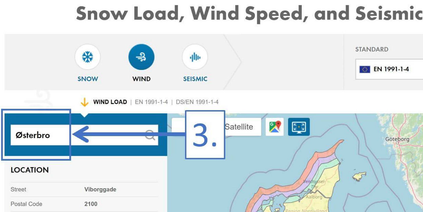
3. Step: Type in the location of the structure
Østerbro is the district in Copenhagen where I live. ✌️😄
For an office building located in Copenhagen, Denmark, we get a fundamental value of the basic wind velocity of:
3. Orography factor c0
EN 1991-1-4 4.3.1 (1) recommends the Orography factor to be taken as 1.0:
💡💡 This value may be defined differently in the National Annex of your country. So double-check if that is the case. 💡💡
4. Turbulence factor kl
As for the Orography factor, EN 1991-1-4 4.4 (4.7) recommends also the turbulence factor to be takes as 1.0.
Again also this value may be defined differently in the National Annex of your country. So double-check if that is the case.
5. Density of air ρ
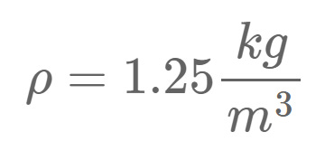
The recommended value for the density of air is given in EN 1991-1-4 4.5 (1) and it is 1.25 kg/m3.
6. Reference height terrain category II z0.II
The reference height of terrain category II is used to calculate the terrain factor kr. The value can be found in EN 1991-1-4 Table 4.1.
7. Roughness length z0
The roughness length is also used to calculate the terrain factor kr.
The value depends on the terrain category where our building or structure is located. The value can also be found in EN 1991-1-4 Table 4.1.
In our case, we assume that our office building is located in a suburban terrain with regular cover of buildings.
Therefore, the building falls into terrain category III.
8. Terrain factor kr
The formula to calculate can be found in EN 1991-1-4 (4.5).
Inserting the values of z0.II and z0 leads to:
9. Turbulence intensity Iv
The turbulence intensity is calculated with EN 1991-1-4 (4.7).
leading to
10. Roughness factor cr
The roughness factor is calculated with EN 1991-1-4 (4.4):
leading to:
11. Mean wind velocity vm
The mean wind velocity is calculated by EN 1991-1-4 (4.3) as:
leading to a mean wind velocity of:
12. Peak velocity pressure qp
The mean wind velocity is calculated by EN 1991-1-4 (4.8) as:
leading to a peak velocity pressure of
Conclusion
For a building with the height of 17.1 m in a suburban area in Copenhagen, Denmark, the wind load can be calculated with a peak velocity pressure of qp = 0.746 kN/m2.
And that is exactly what we do in the episodes of the next 2 weeks.
If you missed episode #1, #2 or #3 of this new series, then you can find all previous posts → here ←.
Have a great rest of the week.
Until next Wednesday. 🙋♂️🙋♂️
Cheers,
Laurin. 😎😎
Enjoy the newsletter? Please forward to a friend you think could like our structural engineering content. It only takes 14 seconds. Making this one took a few hours. Just forward this link: https://www.structuralbasics.com/newsletter/


Thanks, Laurin, for the great series.
It would be interesting to see the wind load on a circular or elliptical structure using the Force Coefficient Method. I'm curious to understand how pressure and suction act on these structures.