

Impact Loads From Vehicles
Episode #11 of the Structural Loads Series

Hi friends, ✌️✌️
When we design a building close to a street where in theory a vehicle could drive into the building, then walls and columns need to be designed for impact loads from these vehicles like trucks.
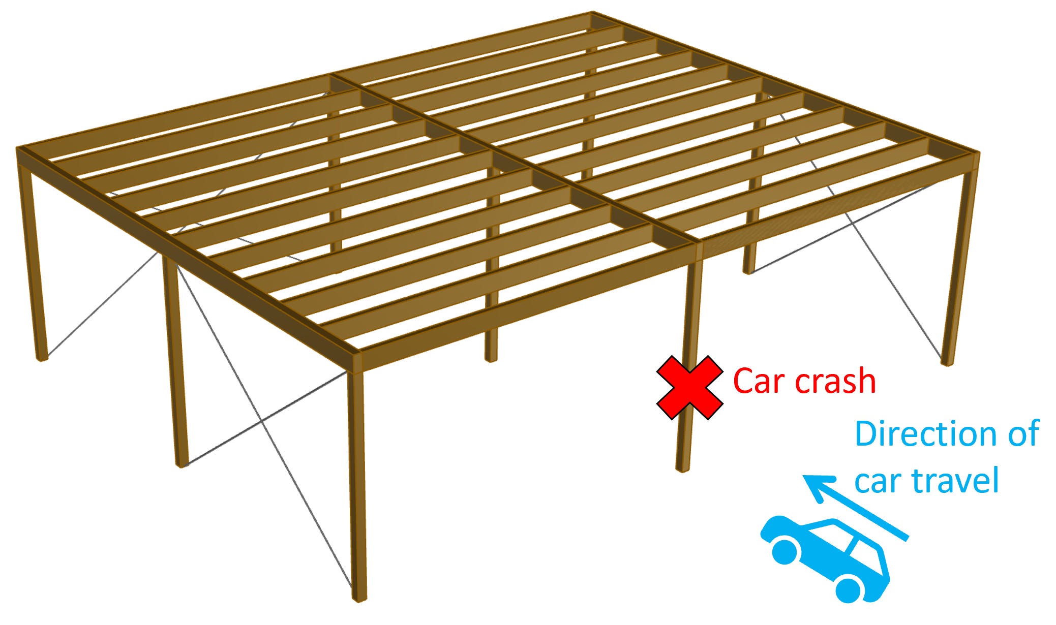
Or, an even more likely scenario: A column of a carport needs to withstand the horizontal load that a car exerts on the column when crashing into the column.
According to Eurocode (EN 1991-1-7 4.2 (1)) these impacts from vehicles need to be considered in the structural design by either dynamic analysis or an equivalent static force.
In the projects I’ve worked on, we always chose to use an equivalent static force. This is quicker and easier as the load values are given in EN 1991-1-7 Table 4.1 and Table 4.2 for different traffic categories. That’s also the method, we’ll explain in this article.
So, in today’s article, you’ll learn
impacts on substructures and superstructures
how to define impact loads and
how to apply it on columns and walls according to Eurocode
As always, we’ll explain with examples and many pictures.
8 Must-Have Tools For Structural Engineers
Most of us structural engineers sit in front of a computer 95% of our time designing and verifying structures with different software programs (hopefully).
So, it really makes a difference in our productivity if we save 1 hour a week because of a better software or because of a software (in case you didn’t use any before).
Here is my list of the 8 must-have tools every engineer should have in 2024.
Now, back to impact loads…
#1 Impact Loads on Substructures
Examples of supporting substructures are according to EN 1991-1-7 4.3.1 (1) are:
columns and
walls of bridges or buildings
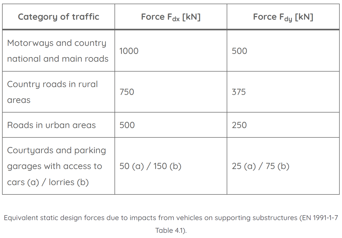
In the structural design, these columns and walls need to be checked for an impact load Fdx in the direction of normal travel and Fdy perpendicular to normal travel. Now, for everyone who isn’t a native English speaker (I didn’t know it either), normal travel means in the direction of the car. Both Fdx and Fdy are defined in EN 1991-1-7 Table 4.1 or in “our table” in the section #3.
If we look at the example of a canopy / carport with some columns, Fdx is the load applied in the direction of the car and Fdy perpendicular to this. We’ll look at the precise location of where the load has to be applied in one of the next sections.

#2 Impact Loads On Superstructures
A superstructure is mainly referred to bridges. Part of bridge superstructures are the deck, cables, arches, etc. Basically anything above the substructure which are supports like abutments, piers and bearings.
Impact loads on superstructures result for example from accidents where a truck is taller than the opening of a frame bridge and drives into it. You probably have already seen such an incident?

In the structural design, the bridge (its static and structural system) needs to be verified for an impact load Fdx in the direction of normal travel of the vehicle. The value of Fdx is defined in EN 1991-1-7 Table 4.2 or in the table in section #3.
Now, let’s look at the values of these impact loads…
#3 Values Of Impact Loads According To Eurocode
The equivalent static impact loads defined in Eurocode are summarized in the 2 tables below.
Note that these values are from the general Eurocode and could be defined differently in the National Annex of the country the structure is located in.
Impact loads on substructures like columns and walls according to EN 1991-1-7 Table 4.1
Impact loads on superstructures of bridges according to EN 1991-1-7 Table 4.2

#4 How To Apply Impact Loads On Columns And Walls
According to EN 1991-1-7 4.3.1 (3) the impact loads Fdx and Fdy should be applied at a height of 0.5m to 1.5m above the level of the pavement and the recommended application area is a = 0.5m in height and 1.5m in width.
Now, columns are of course in most cases not 1.5m wide, then the load is applied on the width of the column. Or, because columns are designed as beams, the load can be applied as a point load or as a line load with width (=a) =0.5m.
Let’s visualize these loads in 3D.
Impact loads on columns

Impact loads on walls

Fdx is applied to the wall as an area load. This helps distribute the load. Also, in case you design the wall with a finite element program using an area load instead of a point load also helps avoid singularities.
The area load is calculated as:

With,
Fdx.a = The area impact load in direction x
Fdx.p = The point impact load in direction x defined in the table in the next section
w = Width of the impact load. In the example above, w = 1.5m
a = Height of the impact load. In the example above, a = 0.5m
But you should always consider the most critical area. In the example from above, that would be the wall column between the 2 openings. It’s more critical because the cross-section is smaller due to a smaller width.
Final Words
Looking at the values of the impact loads, their influence on the design of structural elements close to a street can be quite significant.
You can check out Dlubal’s article where they show another calculation method which results in smaller impact loads from vehicles.
This was it! The last type of structural load we cover in this series. ✌️✌️
However, this series isn’t fully finished yet. In structural design we always verify elements like beams, columns and slab with design loads which are the result of combining different loads with safety factors. So, next week, we’ll cover load combinations.
If you missed episode #1 - #10 of this series, then you can find all previous posts → here ←.
See you next Wednesday, friends. 🙋♂️🙋♂️
Cheers,
Laurin. 😎😎