

Wind Loads On Flat Roofs
Episode #6 of the Structural Loads Series

Hello friends, 🙋♂️🙋♂️
Today, we continue our journey of calculating the wind load.
But compared to wind loads on walls, the wind loads on flat roofs are vertical loads. So, they are used in the design and verification of elements like slabs, beams, columns and walls.

Let’s get into it. 🚀🚀
Step-By-Step Process Of Calculating The Wind Load On Flat Roofs
In order to calculate the wind load or wind pressure on flat roofs, we are going to do the following steps:
Calculate the peak velocity pressure qp
Define the outer geometry of the building (width, height, length)
Calculate the width of the wind areas
Find the external pressure coefficients from Eurocode
Calculate the wind pressures/loads on the flat roof
Example Building
We’ll use the same example building as in the last 2 weeks to show all the steps of calculating the wind load on the flat roof.

#1 Peak Velocity Pressure
We calculated the peak velocity pressure 2 weeks ago as:
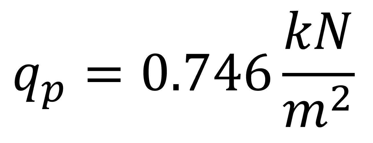
If you missed that newsletter, then you’ll find it → here ←.
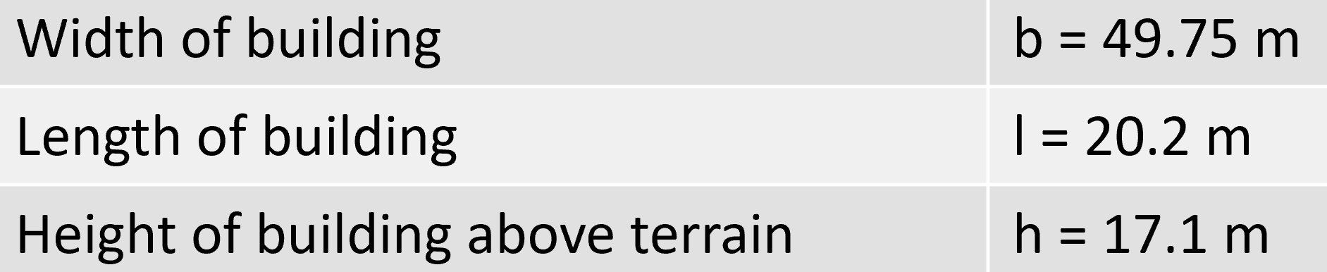
#2 Define the outer geometry of the building (width, height, length)
The building has the following dimensions:

#3 Calculation Of The Width Of The Wind Areas
The wind load on walls is split up in 4 different areas according to EN 1991-1-4 Figure 7.6.
Wind in transverse direction
According to EN 11991-1-4, the width and length of the building (parameter d) for wind in transverse direction are defined as following:

From those dimensions we can define e which determines the dimensions of areas F, G, H and I according to EN 1991-1-4 Figure 7.6.

From e we get the dimensions of the areas according to EN 1991-1-4:2005 Figure 7.6.

This leads to the following wind load areas.

To better understand this, here’s a 3D representation of the wind load areas.

Wind in longitudinal direction
For wind in longitudinal direction, we have to define the area widths again. We have to redefine the geometry parameters.

From those dimensions we can define e according to EN 1991-1-4 Figure 7.6.

From e we get the dimensions of the areas according to EN 1991-1-4:2005 Figure 7.6.

Let’s visualize that.

#4 Find The External Pressure Coefficients From Eurocode
First, here’s the formula to calculate the characteristic wind load (it’s the same as for wind loads on walls):

Where,

So, here in #4, we’ll find the values of cpe for the different wind load areas.
The coefficient cpe has 2 different values depending on the wind loaded area. There is value for a surface area of 1 m2 and 10 m2. These to values can also be written as
For the analysis of the overall stability of a building, we’ll use the external pressure coefficient for areas > 10 m2 (like in this newsletter). The value for surface areas of 1 m2 is used for small elements like roof tiles, parts of a facade, etc.
EN 1991-1-4 Table 7.1 gives recommendations for cpe. This means that you have to double-check with your national annex because those values might be defined differently there.
Pressure coefficients for wind in transverse direction
The external pressure coefficient also depends on the roof type. The following roof types are included:
Sharp eaves
With parapets
Curved eaves and
Mansard eaves
For the roof type of parapet with the parapet height hp = 50 cm, we calculate

to then look up the external pressure coefficients for our areas.
The external pressure coefficients for rectangular buildings can be taken from EN 1991-1-4 Table 7.2.

Don’t be confused by the + and – of the coefficients of Area I. EN 1991-1-4:2005 Table 7.2 Note 3 says that in Area I both positive and negative value should be considered.
Pressure coefficients for wind in longitudinal direction
For the roof type of parapet with the parapet height ratio ℎ𝑝/ℎ=0.03 we can look up the external pressure coefficients for rectangular buildings in EN 1991-1-4:2005 Table 7.2.

#5 Calculation Of The Wind Load
Based on the pressure coefficients, we found in #4 and the peak velocity pressure qp we can now calculate the wind load of the 5 wind areas.
Transverse direction

When you calculate the wind loads the first time ever, it might be very confusing in which direction you have to apply the loads. So let’s apply the wind loads with the cpe.10 coefficient (for 10 m2) on our building.

Longitudinal direction

Those wind area loads we can now visualize.

Conclusion
For a building with the height of 17.1 m in a suburban area in Copenhagen, Denmark, the wind load on the flat roof is calculated for 4 different areas and 2 wind directions.
Next week, we’ll check out how to calculate the wind load on pitched roofs.
If you missed episode #1, #2, #3, #4 or #5 of this new series, then you can find all previous posts → here ←.
Have a great rest of the week.
Until next Wednesday. 🙋♂️🙋♂️
Cheers,
Laurin. 😎😎
Enjoy the newsletter? Please forward to a friend you think could like our structural engineering content. It only takes 14 seconds. Making this one took a few hours. Just forward this link: https://www.structuralbasics.com/newsletter/