


Hi friends,
I recently got a very interesting question from one of you:
→ How do you calculate the load bearing capacity of a double timber beam? Can you use the full cross-section? ←
I published a full, in-depth blog post about it on Monday. Check it out → here ←.
So if you also have a question about a structural design or system, then write a comment below. ✍️✍️
The quick answer to whether you can utilize the full cross-section is: Yes, if the connectors can transfer the horizontal shear from one beam to the other.

In this post, we’ll quickly run through the verification steps you have to do: 👇👇
Bending verification
Shear verification
Deflection verification
Connector design
#1 Bending verification
Now, all the following verifications are done with the assumption that the cross-section consists of both beams.
The bending verification is exactly like for any other timber beam.
Bending stress:

Bending resistance:

Utilization (EN 1995-1-1 (6.11)):

#2 Shear verification
As for bending, the shear verification is also done as for normal timber beams.
Shear stress:

Shear resistance:

Utilization (EN 1995-1-1 (6.13)):

#3 Deflection verification
We need to verify the instantaneous and final deflection criteria.
Instantaneous deflection of double beam:

Btw. you can always use that formula to calculate the deflection of simply supported beams exposed to line loads. In the case that you have unsymmetrical loading, I recommend using a beam analysis software like Polybeam. There are also many programs for free. Just google. 😊😊
Instantaneous deflection criteria (EN 1995-1-1 Table 7.2):

Utilization:

The final deflection is calculated by adding the creep deflection to the instantaneous deflection.
Creep deflection – dead load:

Creep deflection – live load:

Final deflection:

Final deflection criteria (EN 1995-1-1 Table 7.2):

Utilization:

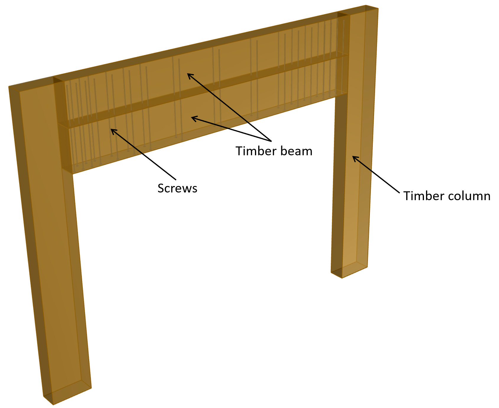
#4 Connection design
The most important part is the connection design. We need to make sure that the shear forces between the 2 beams are transferred from one beam to the other. Otherwise, we could not calculate the bending, shear and deflection as one solid cross-section.
I’ll leave out some of the steps. Otherwise, this email would be too long. But you can see all the required steps in the blog post.
We first calculate the shear force per meter to know which action the connectors need to resist.

Then, we’ll calculate strength parameters of the connection.
Characteristic embedment strength (ETA-11/0030):

Characteristic withdrawal capacity of 1 screw (ETA-11/0030):

Characteristic head pull-through capacity (ETA-11/0030):

Then, we’ll calculate the shear capacity of 1 screw as a timber-to-timber connection with one shear plane according to EN 1995-1-1 (8.6).

Characteristic shear strength of 1 fastener:

Design shear resistance 1 fastener:

We define the spacing of the screws:
And the number of screws per width:
Now, we can calculate the design resistance per meter as:

Utilization:
With the chosen fasteners, we can assume that the 2 beams work as 1 beam, because the horizontal shear forces are transferred from one beam to the other.
I had a lot of fun, calculating and designing this timber beam as it’s a solution you don’t see every day and as it also requires some creativity.
Hope you learned something from it.
See you next week for another structural design guide.
Cheers,
Laurin ✌️✌️
Great post Laurin! There are many tricky aspects to timber design, would be great to see more posts like this, with clear articulation of the design process. What are your preferred timber design tools and resources? I use the Wood Design Manual by the Canadian Wood Council. https://webstore.cwc.ca/product/wood-design-manual-2020/