


Hi friends,
Today we are not talking about reinforced concrete but instead about how we can understand static systems (cantilevers, continuous beams, shear walls, tension rods, etc.) better with physical models.
An amazing resource to build you own structural models is Mola. It’s kind of Lego for structural engineers.
I wanted to get a MOLA Kit for a long time, because it’s a great way to teach and understand the behaviour of static systems. But until now I never had the time to look into it. That’s why I am super happy to share that they reached out and send over one of their KIT’s.
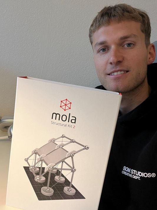
In today’s newsletter, we’ll introduce all structural elements and connections of the Mola Structural Kit 2, model a cantilever beam, a continuous beam and a 3D system (which could be a building) to investigate stabilizing elements like diaphragms, tension rods and shear walls.
So let’s get into it..
1. Introduction to Mola’s structural elements and connections
There are many different components in Mola 2 which all represent a structural element or connection.

Mola structural kit 2 consists of the following structural elements and connection types:
Base plate represents the soil
Base connections represent pad footings
Springs represent columns, beams and bars
Plates are used as load bearing slabs and walls but also for stabilizing elements such as floor diaphragms and shear walls
Diagonals are tension members used as tension rods / wind braces
Hinge connections are used for all connections. In case we want to make a connection continuous or rigid, we add the respective component
Rigid connections: When we add a rigid connection to a hinge connection, the connection becomes momentstiff
Continuous connections: When we add a continuous connection between 2 horizontal springs/beams, the beam becomes continuous. Note that there is still a difference to the rigid connection, because the connection between column and continuous beam is still a hinge.
Now, let’s look at some models..
2. Modelling a cantilever beam (maybe a different name)
For everyone who needs to catch up on the characteristics of a cantilever beam you can check out → this article ←.
The static system of a cantilever beam is characterized by have a fixed support on one end and no support at the other end.

But there are only a couple of examples where the main structure is a cantilever (e.g. in-situ concrete cores of high-rise buildings, cranes traffic light posts, etc.).
In most cases, the cantilever beam is attached to other structures like balconies, overhangs of roofs, and even aeroplane wings.


The effects on the main structure, a cantilever beam is attached to can differ depending on how the fixed support/connection is executed. This is something we can visualize very well with Mola.
How do we model a cantilever with Mola?
Let’s look at cantilever beams that are connected to other structures like walls, slabs, beams and columns.
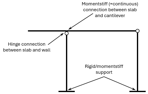
For that we model a 2d frame with 2 columns, 1 beam connected to each other by hinges and 2 rigid (=momentstiff) supports. To make the frame stable out-of-plane, we add 2 tension rods. This represents our primary structure. Let’s say we want to visualize a balcony connected to a building. In this case, the horizontal element is a slab and the vertical elements the walls.

Here’s the static system of this 2d frame:

Now, we add the balcony (=spring) to one of the corners. One of the great things about Mola is that we can quickly identify unstable systems. If we only add a horizontal spring and push on it, we see that the beam “collapses”, because we only have a beam with a hinge connection.

Let’s add some moment stiffness to the connection. We have 2 options:
Fix the balcony/cantilever to the wall or
Fix it to the slab
Cantilever beam rigidly connected to the wall
We add a momentstiff connection between column and cantilever beam and push on the end of the cantilever beam to simulate a point load.

Here’s the deformed shape of the structure.

Cantilever beam rigidly connected to the slab
We add a continuous connection between beam (=slab) and cantilever and push again on the end of the cantilever beam to simulate a point load.
Now, the static system looks like this:
Here’s the deformed shape of the structure.

Why is this important to know?
Different static systems lead to different internal forces. If you use a wrong static system, you might underestimate the internal forces of the walls or slabs. And this again might lead to underdimensioning of the structural elements and in the worst case scenario to collapse.
3. Modelling a continuous beam
If you want to catch up on continuous beam, then check out → this article ←.
The static system of continuous beams is characterized by having a 1 pin support and 2 or more roller supports for a continuous beam, which means that the beam isn’t split up into 2 parts by a hinge connection.

Some real world-examples of continuous beams are:
roof rafters supported by 3 or more horizontal beams
horizontal beams of a garage supported by 3 or more columns
foundation beams supported by piles


How do we model a cantilever with Mola?
Let’s look at a continuous beam with 3 supports, which are in this case columns.
For that, we model 3 columns with hinges at the top and 2 beams connecting to the hinges. To make the beam continuous, we add a continuous connection to the hinge in the center. To stabilize the system out-of-plane, we add 3 tension rods.
But we need to add some rigidity in-plane, because right now the structure isn’t stable. If we push horizontally on one of the corners, the structure collapses.

Let’s add 2 tension rods. Now the structure is stable. We could also add moment stiff connections to the supports or a shear wall.

Here’s the static system of this 2d system:

If we apply a load on one of the spans, we can again investigate the deflection and behaviour of the static system.
The advantage of continuous beams over simply supported beams is that they have a much smaller deflection for the same span, load and cross-section, because the other span is taking up some of the forces.
See for yourself.
Deflection of continuous beam

Deflection of simply supported beam

To sum it up, if you have a simply supported beam that verifies in ULS for bending, shear, etc. but not in SLS for the deflection requirements, consider using a continuous beam. The connection might be more expensive, but at the same time you can save material of the beam.
Let’s have a look at the last system..
4. A stable system with a diaphragm, tension rods and shear walls
Maybe you have already realized that I talk a lot about the importance of understanding stability and horizontal load transfer of structures.
That is because our universities spend too little time for it. 95% of the content taught at university is about vertical load bearing systems and elements like slabs, beams, columns, etc.
For example, when I left uni and started my first job as a structural engineer, I didn’t know enough about stabilizing systems and elements. But it’s as important as vertical load bearing systems.
Mola is such a great way to understand stability better.
In this example, we model a 3d structure (could be a building) which isn’t stable in the beginning, and we’ll add stabilizing elements step-by-step.
Stabilizing elements are
floor diaphragms
tension rods / wind braces
moment stiff connections and
shear walls
We start off by modelling 6 columns with hinges at the top and pin supports. We connect all hinges with beams. The vertical bearing system is “stable” meaning that vertical loads applied to beams find their way down to the foundations. They travel from beam to column to foundation and then to the soil (= base plate).

But the system is by no means stable for horizontal loads. By just applying a small horizontal load, the system collapses. To make the 3d system stable, we need to make the
horizontal floor/roof system stable and
the vertical wall/column/beam system stable
Stabilizing the horizontal floor/roof system
The current floor system is not stabile because if we apply a load, it deflects and changes its shape until it collapses.

Now, let’s make it stabile. We can either add a diaphragm which is in many cases already a load bearing element like an in-situ concrete slab or a CLT slab. Or we add tension rods, which are often used for roof structures.
Let’s do both. If we now apply a horizontal load, the floor system keeps it right angles and doesn’t change its shape any more. However, because the vertical stabilizing system isn’t stable yet, the structure still collapses.

To make the vertical system stable, we need to add a minimum of 3 stabilizing elements (shear wall, tension rods or moment stiff connections (=frame)). But these 3 elements mustn’t be in the same grid line.
Let’s start off by adding tension rods and a shear wall on both sides in longitudinal direction. Now the system is stable in longitudinal direction. But not in transverse direction.


Finally, we add moment stiff connections in one of the fields in transverse direction.

Tip: If you only use 1 stabilizing element in transverse direction (shorter direction), I recommend using a shear wall there, because shear walls are much stiffer than wind braces or frames and the horizontal load in that direction will be much greater than in the other direction (because the facade area is larger).
Final words
I am a big fan of Mola’s structural Kit (in case you haven’t noticed yet). I can really recommend their Structural Kits. Especially if you are in your civil or structural engineering bachelors or just learning about structural engineering in your spare time. Like many of you are doing.
I am not just saying this because they send me a Kit for free. It’s a great way to learn about static systems and understand how they behave for different loads and different connection types.
And it’s really fun!
I wish I had one when I was in my first semesters learning everything about static systems. I remember that I had no clue for 4 semesters how these abstract static systems would translate into real structures.
This is one of the main things I am trying to teach you here on Structural Basics: How we turn a static system into a concrete beam with reinforcement or a timber frame. I hope it helps some of you.
I’ll see you next Wednesday the next newsletter.
Let’s design better structures together,
Laurin.
P.S. Have you already seen my YouTube video where I introduce myself and Structural Basics? You can check it out → here ←.
Enjoy the newsletter? Please forward to a friend you think could like our structural engineering content. It only takes 15 seconds. Making this one took a few hours. Just forward this link: https://www.structuralbasics.com/newsletter/