

Trusses
Post #8 of the Engineering Mechanics Series

Happy Wednesday friends, 🙌🙌
The last 2 weeks we covered beams, the simply supported and cantilever beam. How they work and how we calculate their internal forces.
Today we’ll cover the next structural system - the truss.

Here’s what we’ll cover:
The static system of a truss
Different types of trusses
Examples of loading situations
Example hand calculation of internal forces
So let’s get into it. 🚀🚀
The static system of a truss

A traditional truss consists of bar elements connected to each other by hinges in all nodes. Bar elements are different to beams, because they can only take up normal forces. A truss is supported by 1 roller support and 1 pin support, making it statically determinate.
It can be seen from the picture that the support (a) takes up
a vertical reaction force Va and
a horizontal reaction force Ha
The roller support in (b) takes up
a vertical reaction force Vb
Trusses nowadays
Nowadays, the top and bottom chords are often manufactured as one piece, and due to advanced Finite Element programs it’s become easy to design trusses with fixed connections.
You are maybe wondering why the connection type is so important?
It’s because trusses with hinges are statically determinate, which means that we can calculate the internal forces by hand.
The Warren truss with fixed connections however can’t be calculated with the 3 equilibrium equations because it’s statically indeterminate.
So, be aware that the type of connection has an influence on the design of the truss.

A truss with fixed connections has the following differences to hinge connections:
Bending moments in the connections
More rigidity → more robustness
Smaller vertical deflection
Different types of trusses
There are many different types of trusses. We won’t go into detail of the characteristics of the different types in this newsletter, but you can check out our in depth article about the different types of trusses.
Here’s a quick overview of 11 commonly used types of trusses.

Some of them are used as roof structures, some as bridges and some for other long spanning structures. If you type into google different types of trusses, you’ll find more. 🙂🙂
Examples of loading situations
The loading of a truss depends on the type of truss (the load is carried by a different member if the truss is a bridge compared to a roof) and the static system (whether the top and bottom chords are beams or bar elements). Let’s dive into these different scenarios.
Pratt truss used as a bridge structure with hinges
If the Pratt truss is used as a bridge structure, the loads (vertical traffic and dead load) are applied on the bottom chord. In the case that the truss has hinges and the elements are bars, we can’t apply line loads to the static system because bar elements can’t take up bending moments and shear forces. In this case, the line load has to be transferred to point loads and applied to the nodes.

Howe truss used as a bridge structure with beams as bottom chords
Now, if continuous beams are used as bottom and top chords, the load can be applied as a line load because beams can take up bending moments and shear forces. Note that the structure is now statically determinate, and you can’t calculate the internal forces with the 3 equilibrium equations any more.

King post truss as a roof structure with bar elements
The king post truss is mainly used as a roof structure. This truss resists external loads such as snow, dead and live loads. If all members are modelled as bar elements these loads are translated into point loads and applied to the nodes.

Example hand calculation of internal forces
As said earlier, we can only calculate the internal forces of trusses with bar elements and, which are statically indeterminate. That’s what we are going to do in this section.
We’ll use the example of a Howe truss. Let’s say our Howe truss is a bridge structure. Therefore, the truss is exposed to dead and traffic load mainly on the bridge deck, which transfers the loads to the bottom chord.
We also simplify and say that the design load (load combination of dead and traffic load) is 200 kN/m.

Before we start with the calculations, let’s give the nodes 🔵 and bars 🔴 some indices, so the identification is easier later in the internal force calculation.

To calculate the compression and tension forces of the truss members with the 3 equilibrium equations, we do another approximation.
The line load of 200 kN/m is approximated as point loads in the nodes, because our members are bar elements.
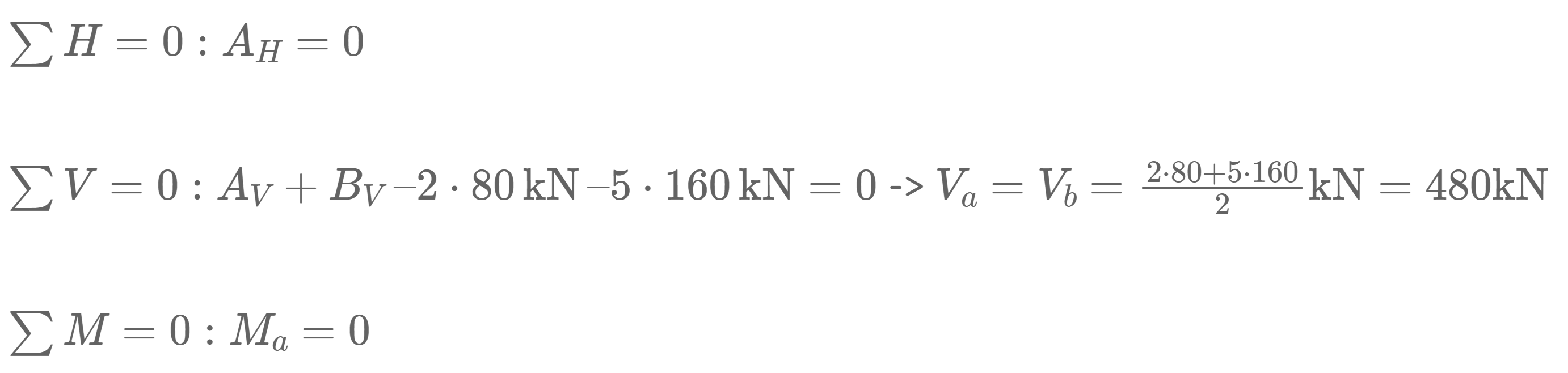
The point load applied to nodes (a) and (g) is calculated as
200kN/m ⋅ 4m=80 kN
while the point loads applied to nodes (b), (c), (d), (e) and (f) is calculated as
200kN/m ⋅ 8m=160 kN

Let’s calculate. 🚀🚀
Calculation of reaction forces
As the structure is statically determinate, the reaction forces can be calculated with the 3 equilibrium equations.
In our case, we are calculating the support forces AH, AV and BV.
Calculation of the internal forces
Alright, now that we know the reaction forces, we can calculate the normal force of the first bar elements 1 and 4.
Node a
To do that, we only look at node 1 and its point loads/normal forces AV, 80 kN, N1 and N7.


Vertical equilibrium:
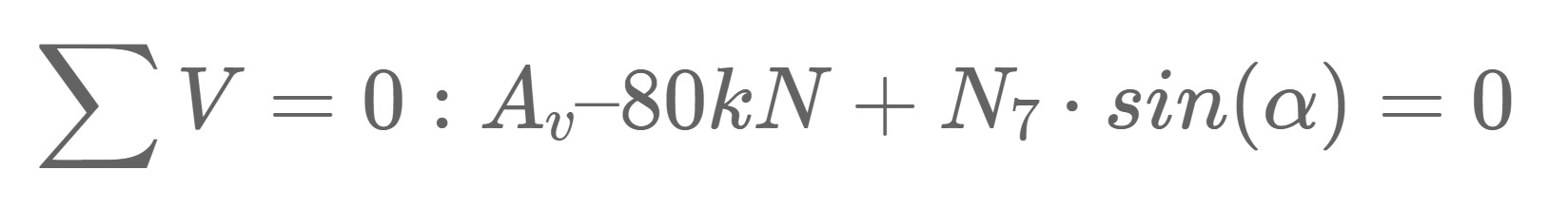
Let’s solve that for N7.

Horizontal Equilibrium:
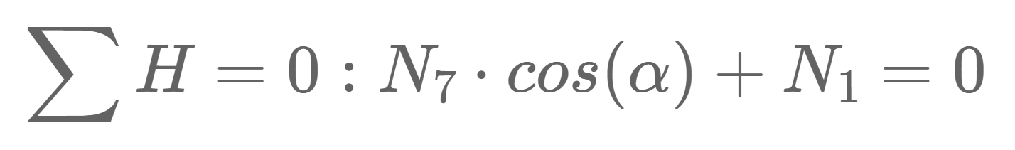
Let’s solve that for N1.

Node h

Vertical Equilibrium:

Let’s solve that for N8.

Horizontal Equilibrium:

Let’s solve that for N18.
Node b
Vertical Equilibrium:

Let’s solve that for N9.

Horizontal Equilibrium:

Let’s solve that for N2.

Node i

Horizontal Equilibrium:

Let’s solve that for N19.

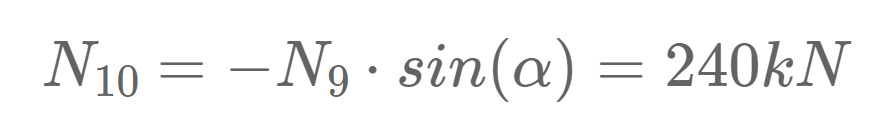
Vertical Equilibrium:

Let’s solve that for N10.
Node c

Vertical Equilibrium:

Let’s solve that for N11.

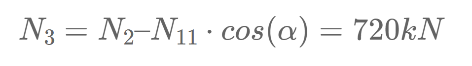
Horizontal Equilibrium:

Let’s solve that for N3.
Node d
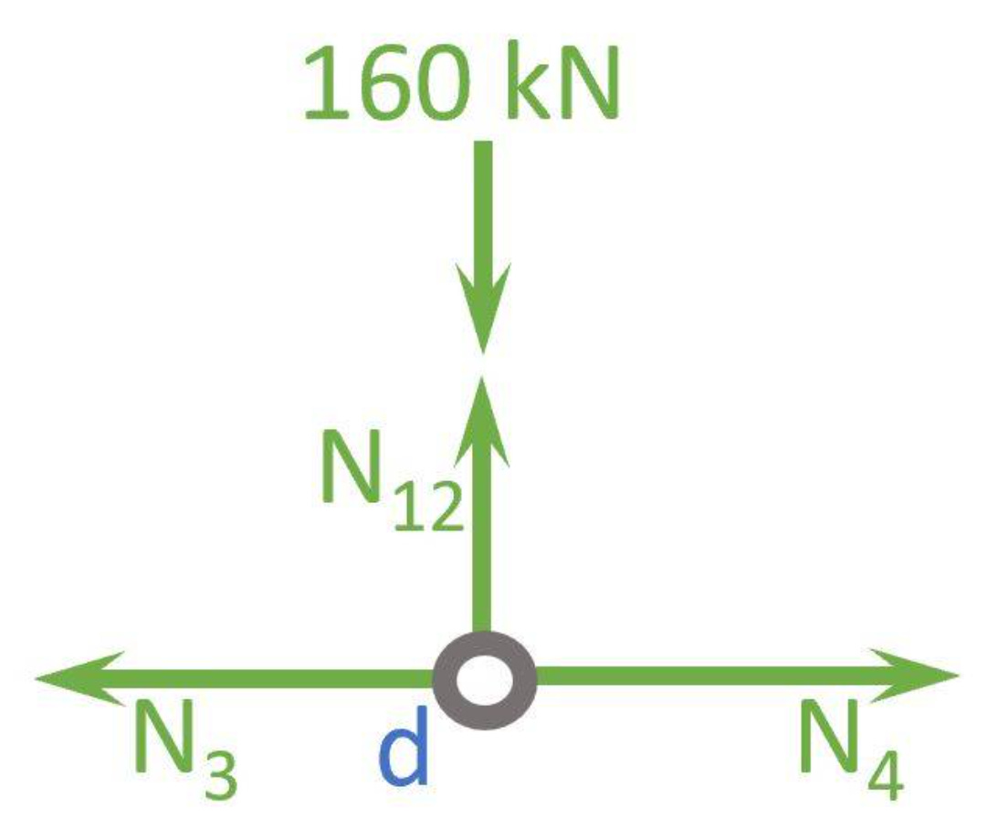
Vertical Equilibrium:
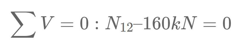
Let’s solve that for N12.

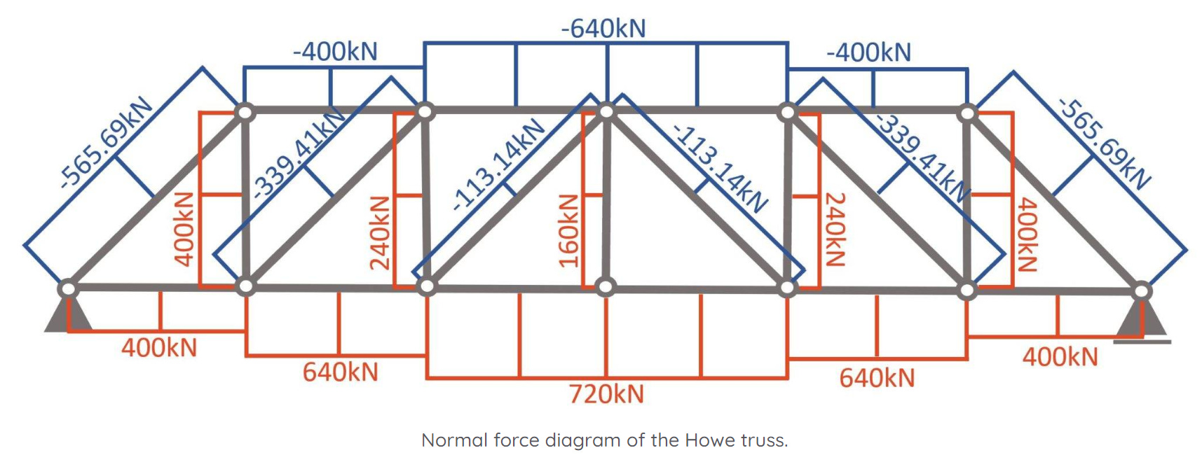
Well done! Now we have calculated the normal forces of ALL bars.🎉🎉
What all? But we are missing half of the bars? Yes! But due to symmetry we know that N1 = N6, N2 = N5, N3 = N4, N7 = N17, N8 = N16, N9 = N15, N10 = N14, N11 = N13, N18 = N21, N19 = N20.
So, to summarize it, a normal force diagram helps to understand how the loads travel through the truss.
Normal force diagram
Conclusion
We wrote this already in the conclusion of the last newsletter, but I’ll repeat it:
Calculating the internal forces over and over and over again for different static systems is key to understanding the process and making less mistakes. If you’ll become a structural engineer, this will also help you understand the results of software programs better and let’s you find mistakes.
The truss was the 3rd example we looked at. In the next weeks, we’ll look at more examples such as the arches, frames, etc.
This was already the 8th edition of the engineering mechanics series.
See you next Wednesday for another post. 🚀🚀
Have a great rest of the week. ✌️✌️
Cheers,
Laurin.
Thank you M.J. may god bless you
Hi Laurin, I really enjoy reading your emails. Is there any place I could ask for a request? Specifically the design approach and calculations to adding bracing to a structure to account for lateral loads (wind, earthquakes, etc...)