


Hi friends,
We’ll cover the first timber roof structure today, as announced last week. 🚀🚀
The timber rafter roof.

The timber rafter roof consists of:
rafters
ceiling joist (or concrete slab)
ridge board
wind bracing system (steel strap or boards)
collar tie
Now, as for every timber roof, there are many different variants.
Before we’ll get into the design calculations, let’s have a quick look at the static system. 👇👇

Alright, now we are ready. For designing the timber rafters, we can follow a step-by-step process:
Determine the characteristic loads (snow, wind, dead and live load)
Set up load combinations
Choose the timber material and geometry of the rafters (width and height)
Calculation of the internal forces (normal force, shear force, bending moment)
ULS bending and compression verification
ULS shear verification
ULS buckling verification
SLS deflection verification
These are the steps, we need to follow to design the rafters, but there is more to the roof structure such as connection design, wind bracing, and ceiling/slab calculation. This however would now be too much to cover in an e-mail. Let us know in the comments if we should include it in one of our next mails. ✍️✍️
#1 Characteristic loads
We’ve written detailed articles about loads on roof structures, which you can follow to understand how to calculate these loads:
Wind load on pitched roof
Snow load on pitched roof
Dead load
Live load
#2 Load combinations
Load combinations combine the characteristic loads and add safety factors.
→ Detailed guide to load combinations ←
#3 Timber material and geometry of rafters
You choose the timber material between structural wood and glulam. Glulam is usually stronger and can be delivered in almost any size, as it glues layers of timber together.
Just google a bit, and you’ll find the strength properties for both types of timber.
Before starting the calculation, we need to define the cross-sectional dimensions height h and width w of the rafters.

#4 Internal force calculation
In uni, you learn to calculate the internal forces by hand, which is good to get an understanding for it. Later, as a structural engineer, you’ll mainly use software for it. Mainly because it’s alot faster. Programs like Autodesk Robot, Dlubal Rfem, Sofistik, etc. are used.
You apply the characteristic loads, and the programs generate automatically load combinations and the internal forces.

Here’s an example of the bending moment diagram due to load combination from the picture above.

The biggest internal forces M, V and N are then used for the structural design in ULS.
M = 10.6 kNm
V = 8.1 kN
N = 23 kN
#5 ULS bending and compression verification
First, calculate the bending and compression stresses:


Then the bending and compression resistance:

Now, check if the utilization ratio is < 100%

To see the whole calculation with examples, check out our 👉 article 👈.
#6 ULS shear verification
As for bending and compression, we’ll calculate the shear stress and shear resistance.

And then the utilization ratio.

#7 ULS buckling verification
Slenderness ratio

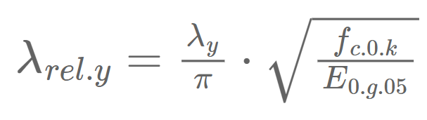
Relative slenderness ratio
Instability factor

Buckling reduction coefficient

Utilization ratio

#8 SLS deflection verification
The deflection is also calculated with structural analysis programs and checked against limits from either Eurocode or the client.
It’s a bit more tricky, I recommend reading the article for more detailed explanations. 😎😎
This was the first timber roof system. Hope you liked it and gained knowledge.
Until next week for the next roof system. 👍👍
Cheers,
Laurin.