Timber Flat Roof
The 3rd Roof Type
Hi friends,
Today we’ll look at one variant of the timber flat roof. 😎😎
Info about next week ℹ️: We’ll take a break from roof systems next week, but cover a structural component that is part of all timber roofs. You can find out which component we’ll cover at the end of this email. 🔚🔚
The flat timber beam roof consists of:
Secondary beams
Primary beams
Roof diaphragm (plywood panels or wind bracing)
Columns or walls to support the beams (roof) and
A wind bracing system like steel rods or shear walls
As for the other roof types, there are many different variants.
Before we’ll get into the design calculations, let’s have a quick look at the static system and how the loads are transferred. 👇👇
The secondary beams are exposed to the loads on the roof and they are simply supported by the primary beams, as you can see in the picture above.
The reaction forces of the simply supported beams are then applied as point loads on the primary beams.
Alright, now we are ready. Here’s the step-by-step process we are following (it’s the same for all timber elements 😁😁):
Determine the characteristic loads (snow, wind, dead and live load)
Set up load combinations
Choose the timber material and geometry of the chords and diagonals (width and height)
Calculation of the internal forces (normal force, shear force, bending moment)
ULS bending verification
ULS shear verification
SLS deflection verification
These are the steps, we need to follow to design the truss, but there is more to the roof structure such as connection design, wind bracing, and support verification.
#1 Characteristic loads
We’ve written detailed articles about loads on roof structures, which you can follow to understand how to calculate these loads:
#2 Load combinations
Load combinations combine the characteristic loads and add safety factors.
→ Detailed guide to load combinations ←
#3 Timber material and geometry of beams
You choose the timber material between structural wood and glulam. Glulam is usually stronger and can be delivered in almost any size, as it glues layers of timber together.
Just google a bit, and you’ll find the strength properties for both types of timber.
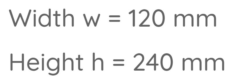
Before starting the calculation, we need to define the cross-sectional dimensions’ height h and width w of the beams to then calculate cross-section properties such as the moment of inertia.
#4 Internal force calculation
Simply supported beams exposed to a uniformly distributed line load are easy to calculate. The max. bending moment is calculated as
M = 1/8 * q * l^2
You apply the design loads, and calculate the internal forces. 👇👇
Here’s an example of the bending moment diagram due to the load combination from the picture above.
#5 ULS bending verification
First, calculate the bending stresses of the beams:
Then, the bending resistance:
Now, check if the utilization ratio is < 100%. ✅✅
To see the whole calculation with examples, check out our 👉 article 👈.
#6 ULS shear verification
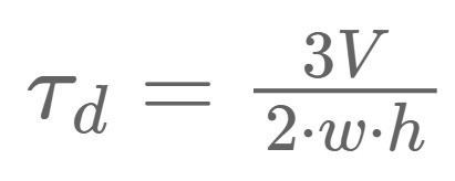
As for bending, we’ll calculate the shear stress and shear resistance.
And then the utilization ratio.
#8 SLS deflection verification
The deflection of simply supported beams exposed to a line load can be calculated with the following formula. 👇👇
The calculated deflection u_inst should now be lower ⬇️⬇️ than the deflection criteria.
The deflection criteria is defined either by your National Eurocode Annex or by the client.
But again, if you want to understand the deflection better, then I recommend reading the article for more detailed explanations. 😎😎
This was the 3rd timber roof system. Hope you also liked this one.
Next week we’ll make a little detour and check out a common steel connection for timber roofs, before we’ll cover the last 2 timber roof systems. 👍👍
Cheers,
Laurin.


