


The Moment Of Inertia Of Cracked Reinforced Concrete Sections
🔥16th and last post of the engineering mechanics series

Happy Wednesday, 🙋♂️🙋♂️
Welcome to the last episode of the engineering mechanics series. 👋👋 We’ve made it. 🔥🔥 Today, is post #16, and I am excited to share content about new topics from next week.
Many new people have joined the Structural Basics newsletter since episode #1. Welcome. It’s great to see the newsletter grow. 🚀🚀 I got many messages, if it’s possible to access previous episodes. And absolutely, here are 2 options how you can access older posts:
1. You can download the Substack app on your phone and create a free account. Then Structural Basics should show up or if not, just search for it. There you have access to all previous newsletters. For free, of course.
2. On a computer, you can find the previous posts here: https://open.substack.com/pub/structuralbasics?r=1vf2bc&utm_medium=ios
Now, let’s get into today’s topic.
Moment Of Inertia Of Cracked Reinforced Concrete Sections
Last week I told you that most reinforced concrete sections of for example beams are cracked and that the stiffness is reduced once a section cracks. Cracks happen, when the tensile stress resistance of concrete is reached. Then the concrete can’t take up any tensile forces any more and the reinforcement gets activated and takes up all tensile forces.
So today, we’ll run through the steps to calculate the moment of inertia of cracked reinforced concrete sections.

So, today we’ll cover:
The step-by-step process of calculating the moment of inertia of cracked cross-sections and
A calculation example
So let’s get into it. 🚀🚀
Calculation Process
Here are the steps, we need to follow to calculate the moment of inertia of a cracked rectangular reinforced concrete section (we’ll calculate and define all parameters in the next section):

Define the geometrical and material properties of the reinforced concrete section (Longitudinal reinforcement at bottom and top, E-moduli of steel and concrete, cross-sectional dimensions, etc.)
Ratio between moduli:

Height of the compression area


Moment of inertia (composite rectangular section)


Calculation Example
Now, let’s apply this to an example with the following geometrical and material parameters:

Geometrical parameters

Material parameters
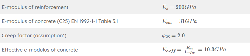
1. First, we’ll calculate the ratio between the reinforcement and concrete moduli:

There you can see that the reinforcement is 19.4 times “stiffer” if you use the same amount of material.
2. Next, we’ll calculate the depth of the neutral axis x of the cracked section:

We’ll find the depth of the neutral axis by equilibrium of the first moment of areas of the tension (steel) and compression (triangle). But don’t get confused by the triangle here. When calculating the static moment of the compression zone, we only need the area of it and the lever arm is x/2.
Equilibrium of the 1. moment of areas:

Now, let’s solve that equation for x to get the height of the compression area:

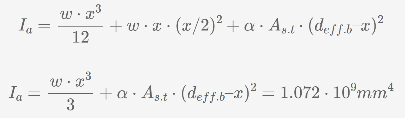
3. Then, as the last step, the moment of inertia of the cracked section:
Conclusion
That was it! We are done with the engineering mechanics series.
Hope, you liked the series and learned something?
As already announced 4 weeks ago, we’ll continue our journey by diving deep into loads and loads combinations. Loads and engineering mechanics are the foundation of structural design.
I am excited, are you?
See you next Wednesday. 🚀🚀
Have a great rest of the week and a great weekend. ✌️✌️
Cheers,
Laurin.
Enjoy the newsletter? Please forward to a friend you think could like our structural engineering content. It only takes 14 seconds. Making this one took a few hours. Just forward this link: https://www.structuralbasics.com/newsletter/