

The Cantilever Beam
Post #7 of the Engineering Mechanics Series

Hi friends, ✌️✌️
Last week we looked at the simply supported beam, how it works, and how we calculate its internal forces.
Today we’ll cover the next example - the cantilever beam.
Here’s what we’ll cover:
Real-life examples of cantilever beams
The static system of a cantilever
Examples of loading situations
Example hand calculation of internal forces
So let’s get into it. 🚀🚀
Real-life examples of cantilever beams
It’s always good to know where and how these theoretical “models” are used in real-life, isn’t it?
Here are 11 examples:
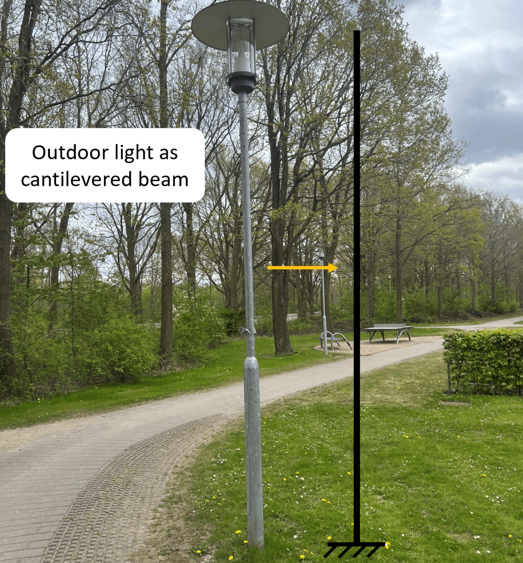
Traffic light posts and systems cantilevering over the street
Street lamp

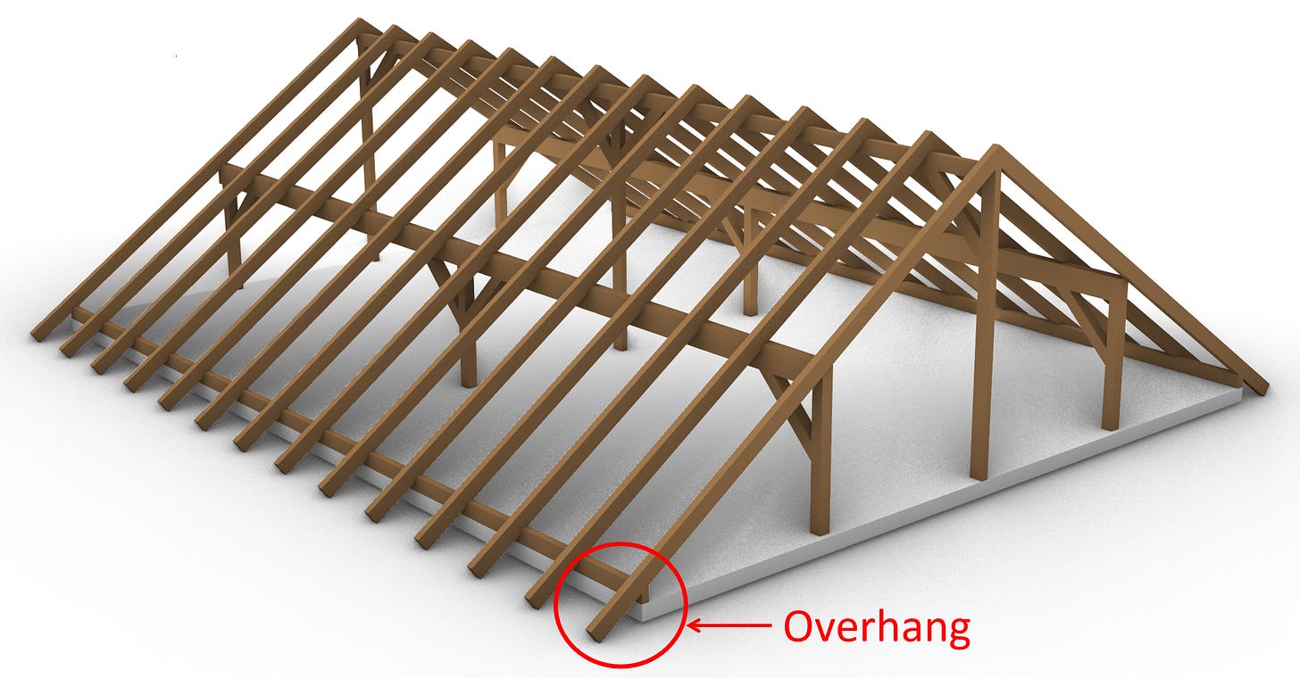
Overhangs of roofs
Bridges during construction using the balanced cantilever method
Balconies

Aeroplane wings
Side mirrors on a car
High-rise buildings (vertical cantilevers)

Bookshelves attached to the wall
Cranes 🏗️🏗️
Wind turbine blades


And there are so many more examples. Last week I told you that roughly 80% of the static systems I design as a structural engineer are simply supported beams. Another 10% are cantilever beams. So knowing how to calculate the reaction and internal forces is important in structural engineering. And as you could see from the examples above, cantilever beams are part of our everyday life.
Quick recap of the static system
We’ve already shown the characteristics of the cantilever beam in earlier posts, but repetition is always good.

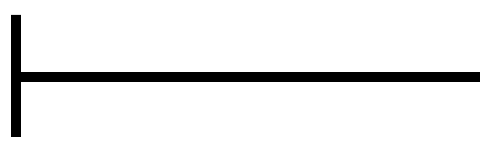
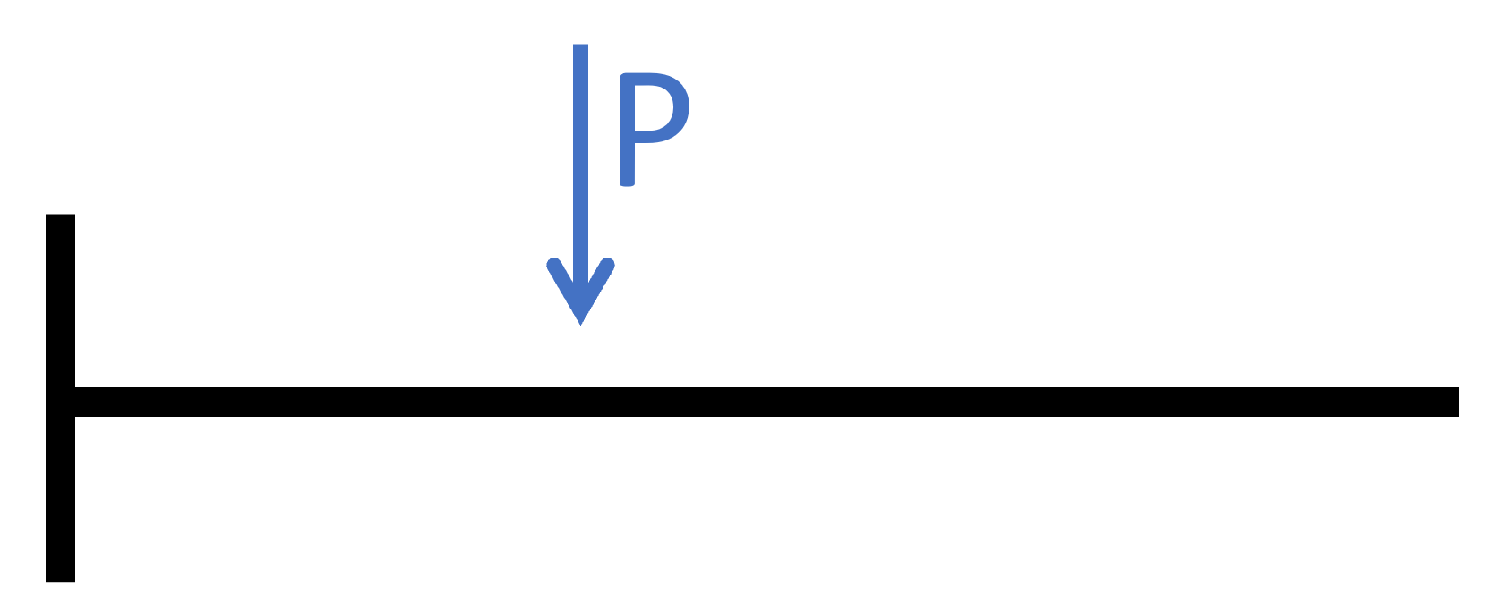
The cantilever beam is in most cases a horizontal beam having one fixed support on one end. The beam can take normal and shear forces, as well as bending moments.
It can be seen from the picture that the fixed support (a) takes up
a vertical reaction force Va
a horizontal reaction force Ha and
a bending moment Ma
Examples of loading situations
Loads act on static systems. These loads result in reaction and internal forces such as bending moments, shear and normal forces. If there weren’t any loads acting on a static system, then the internal forces would also be 0.
Line loads
Line loads on the cantilever beam are loads of the same value along a certain distance. An example is the self-weight/ dead load of a beam. If the beam is a timber beam, the line load is calculated as density * cross-sectional width * cross-sectional height.
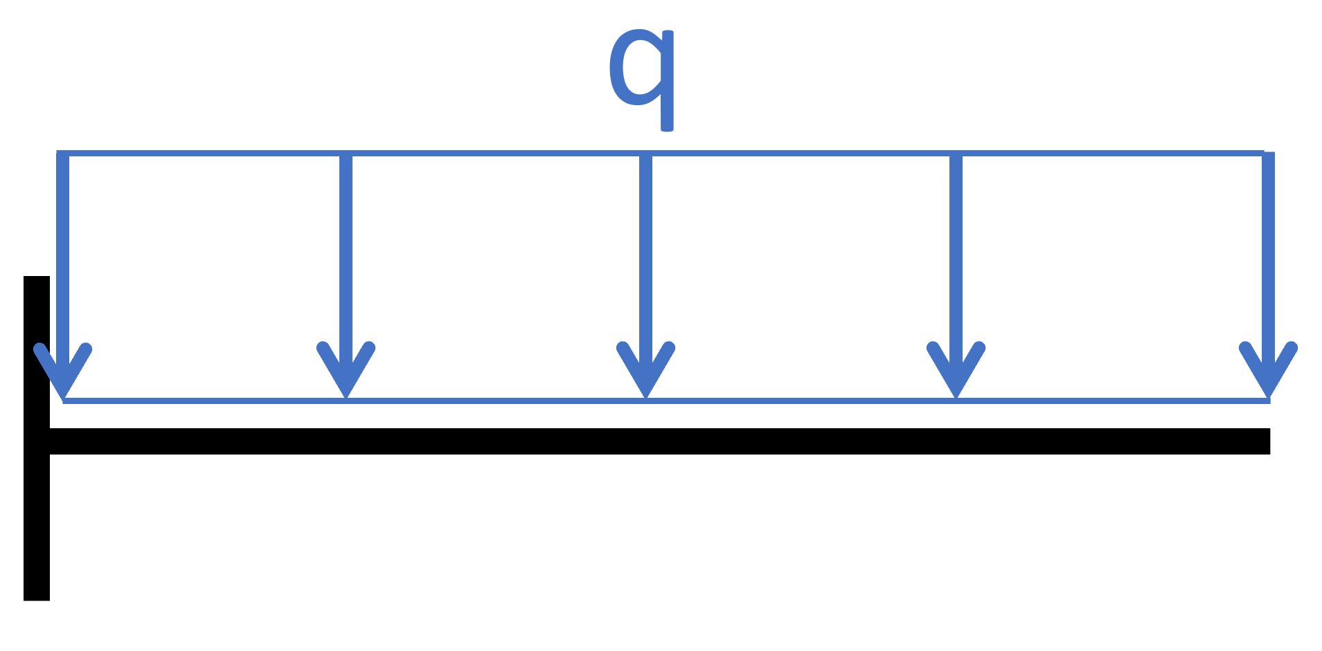
Other line loads could be the live load of a balcony representing people. Then the line load which is applied on the beam is calculated as area live load * 1m if the balcony is calculated as a beam with width 1m.
Point loads
Point loads are concentrated loads that are applied on the cantilever beam in one point.
An example could be a person’s weight, like mine 😁😁 when standing on a balcony.

Now, there are more loads we could apply to a cantilever beam, like an external moment or a triangular line load. But line and point load are the most common.
Check out this → guide ← if you want to see a summary of all loads.
Now, let’s get into the hand calculations. 🔥🔥
Example hand calculation of internal forces
Let’s use the example of the balcony, which I am loading with my body weight. I currently weigh 75 kg. 🙄🙄 This leads to a point load of 0.74 kN to be very precise. The balcony is 1 m in length, and I am standing at 0.75 m.
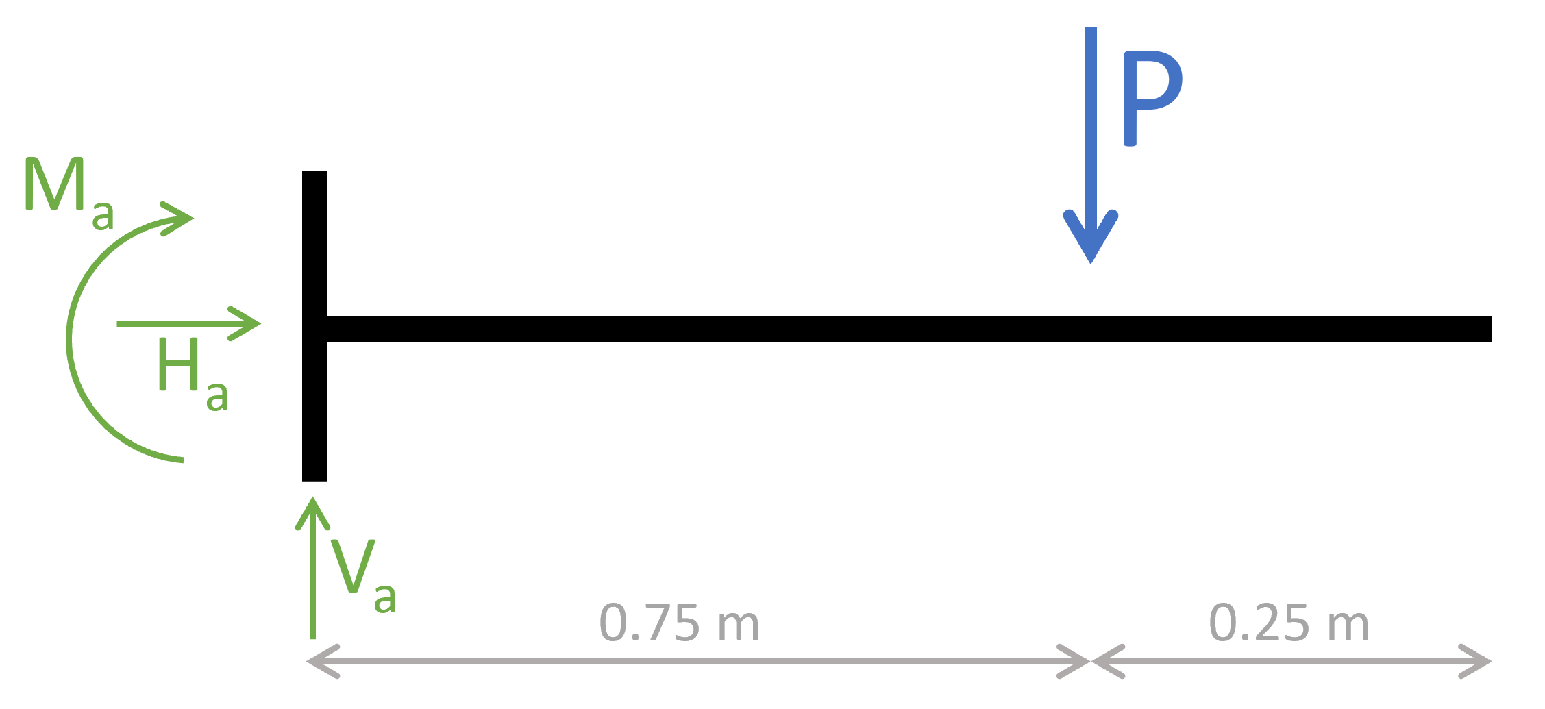
1. The first thing we always calculate in determinate structures are the reaction forces/moment. In our case, that is Ha, Va and Ma at support (a). We’ll use the equilibrium conditions to determine the reactions.


💡💡 The bending moment is negative because of the direction of the moment (the half circle with arrow ↩️↩️) in the picture above. If the opposite direction was used, the moment is positive. 💡💡
2. Based on the reaction forces, the shear and moment distribution along the beam can be calculated. This can also be done without the reaction forces for the cantilevered beam. The parameter x is introduced as the length between point a and any point on the beam.

3. The shear forces and bending moments can be calculated in dependence of x. Let’s make a first cut at a point between the support and the point load 0<x<0.75m.
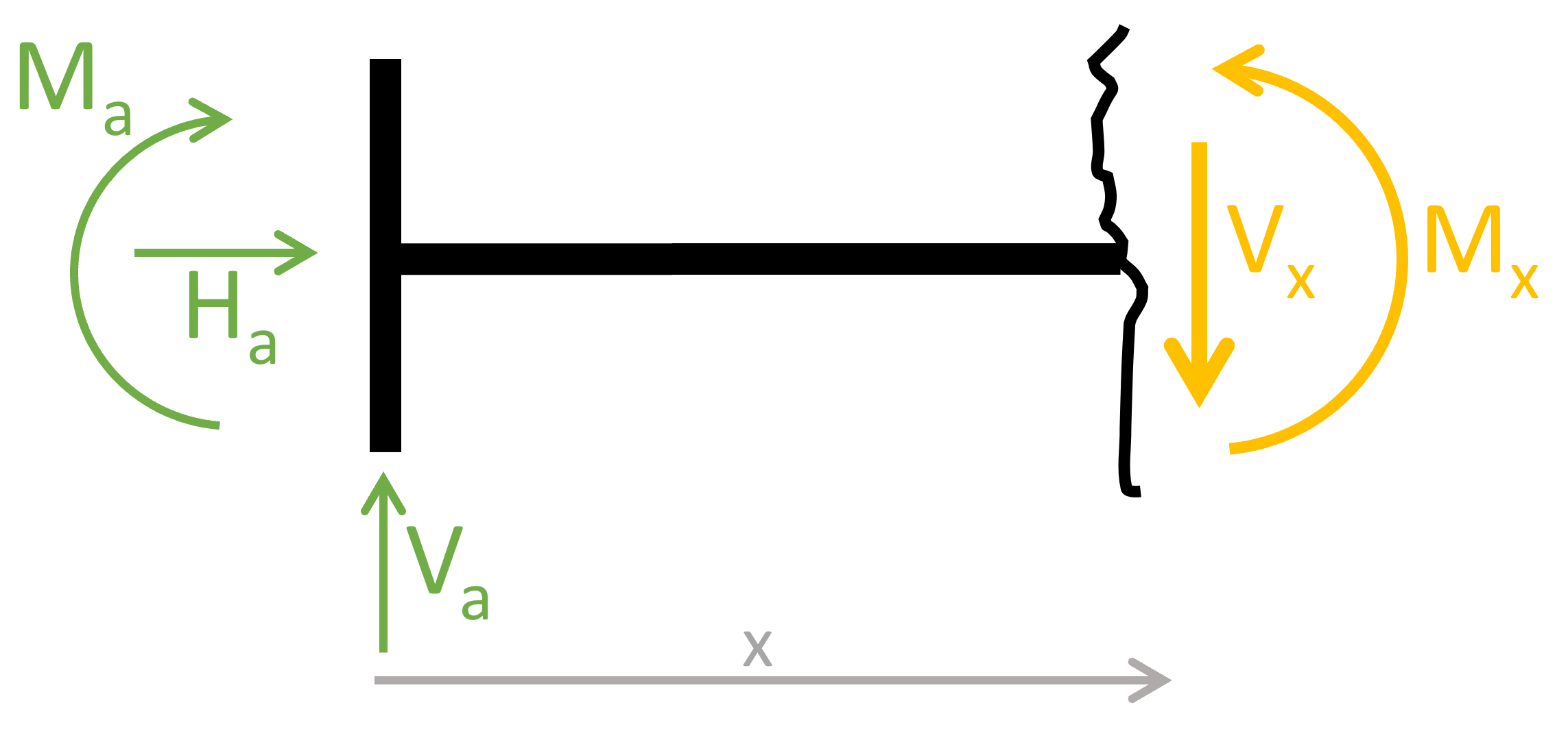
As for the reaction force calculation, the equilibrium conditions are used to calculate the moment and shear forces at point x.


As we can see, the shear force is constant and not dependent on the parameter x. Let’s set x = 0.5m and see what results we get for the bending moment:
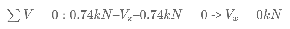
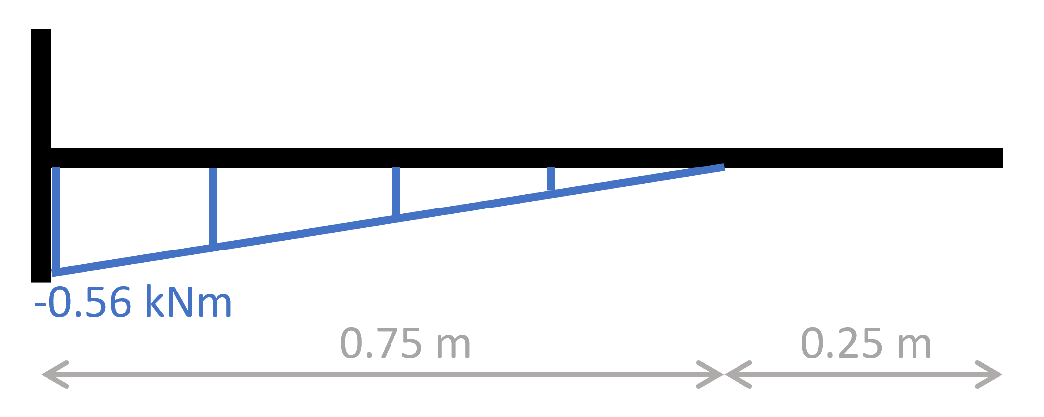
4. Cut at a point between the point load and the endpoint 0 < x < 0.75m.
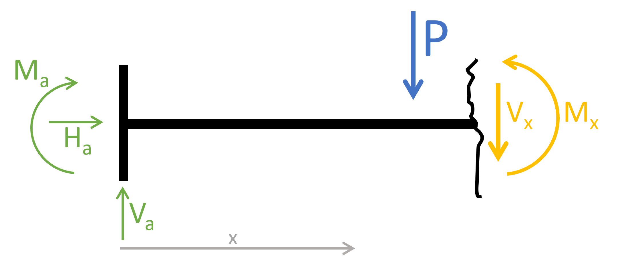
The equilibrium conditions lead to:


5. Lastly, we can draw bending moment and shear force diagrams.
The diagrams can be plotted by a tool like Excel using the formulas from above or drawn by hand.
Or you can also create your own beam analysis program in Python.
Shear force diagram – cantilever beam

Bending moment diagram – cantilever beam
Conclusion
Calculating the internal forces over and over and over again for different static systems is key to understanding the process and making less mistakes. If you’ll become a structural engineer, this will also help you understand the results of software programs better and let’s you find mistakes.
The cantilever beam was the 2nd example we looked at. In the next weeks, we’ll look at more examples such as the arches, trusses, etc.
This was already the 7th edition of the engineering mechanics series.
See you next Wednesday for another post. 😎😎
Have a great rest of the week. ✌️✌️
Cheers,
Laurin.