Shear verification WITH shear reinforcement [reinforced concrete]
Episode #6 of the reinforced concrete series
Welcome back to another Structural Basics newsletter,
Last week, we showed how to verify shear without shear reinforcement of rc beams and slabs. Today, we’ll do the opposite - verify shear WITH shear reinforcement.
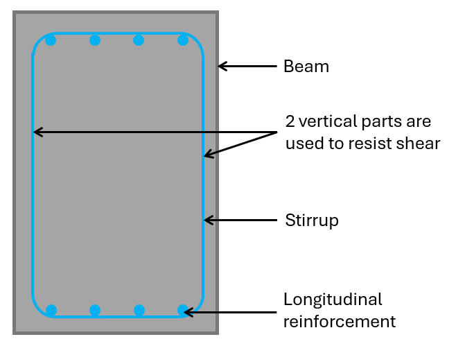
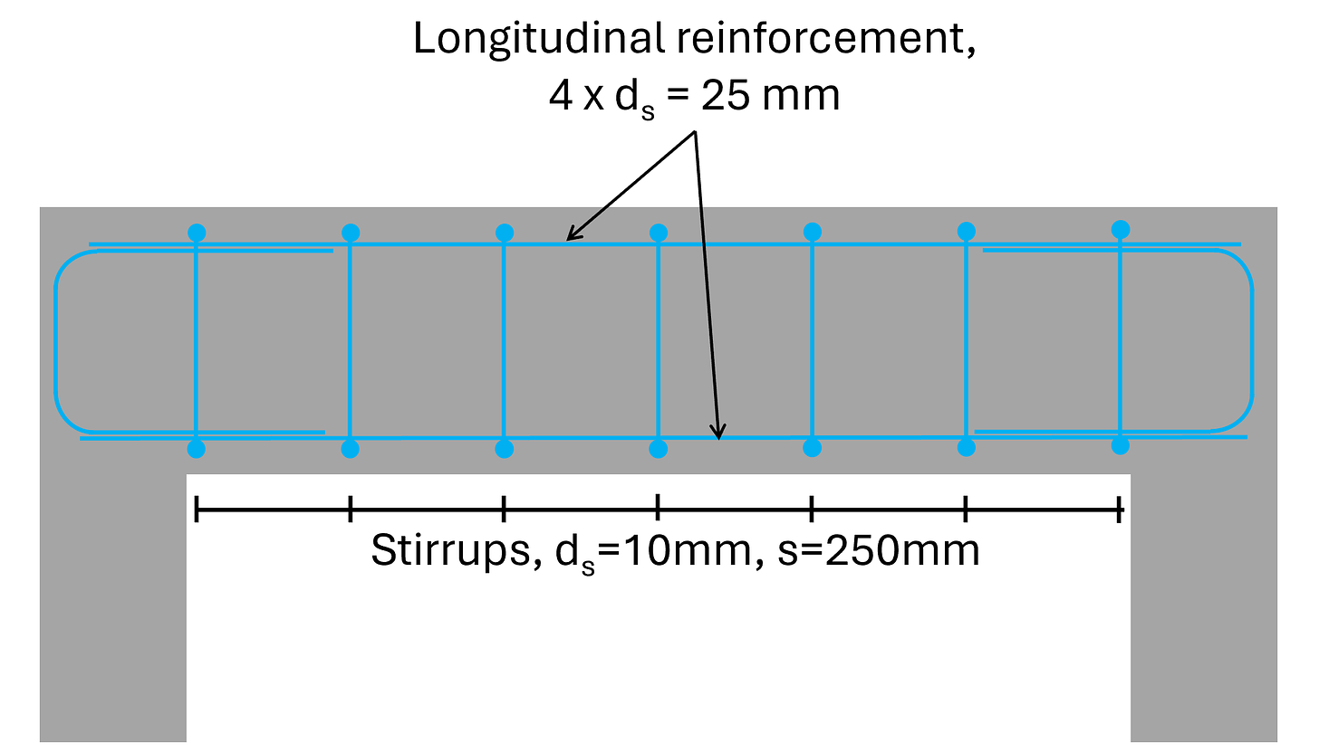
Shear reinforcement are usually vertical rebars. To account for the correct anchorage length, usually closed stirrups, L-shaped or U-shaped rebars are used.
From my experience, construction companies usually rather use L- or U-shaped rebars instead of closed stirrups when connecting 2 elements that are cast at different times.
If your beam is very tall, it also makes sense to split up the closed stirrup into 2 U-shaped rebars to account for tolerances. Imagine having to bend a closed stirrup that is 2 meters in height precisely as the rebar schedule says? Pretty difficult.
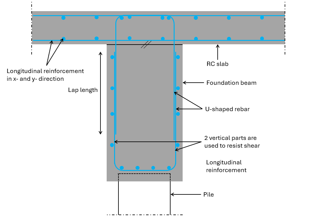
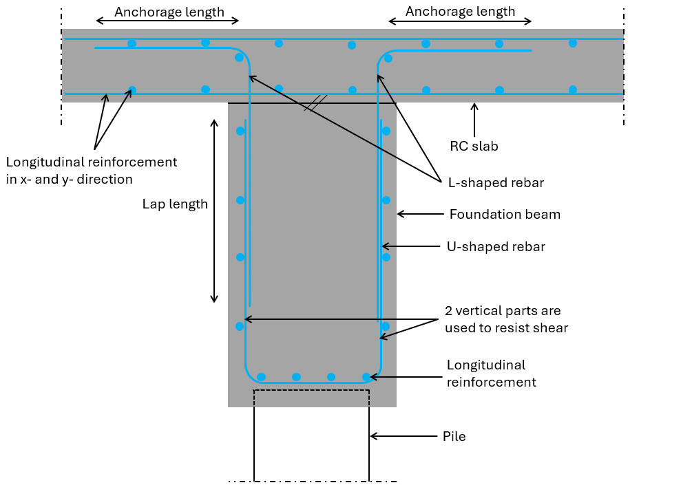
Before deciding on which shape of shear reinforcement you use, ask the contractor which they prefer. They really appreciate structural engineers that think about their work, and a good partnership can be built upon small things like this.
In this newsletter, I’ll explain to you how shear works in reinforced concrete and how to verify and design shear reinforcement of reinforced concrete elements like beams and slabs in 5 steps.
How does shear work in rc beams?
Shear is quite a complex topic. Still, to this day, I am learning new things about it on a regular basis. And it’s shocking to me how many engineers I’ve worked with are unaware of the basic fundamental of shear in reinforced concrete structures. In this section, I’ll give a short introduction to the most important basics (at least to me) of shear and shear design in reinforced concrete elements.
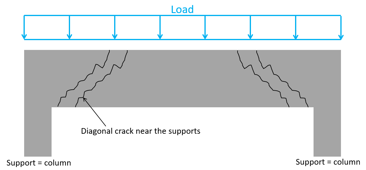
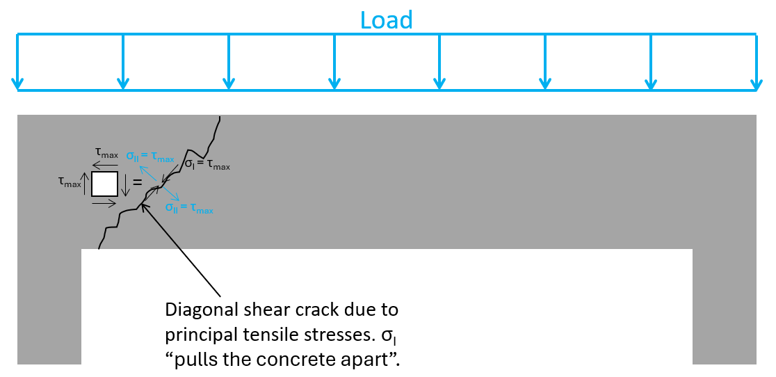
The best way to start is by looking at shear failure of rc beams - or in other terms, where the beam cracks when the shear forces are too big. Shear cracks of beams exposed to a line load appear as diagonal cracks near the supports. Why at the supports? Because that’s where the shear forces are the biggest.
Let’s dive into why this is.
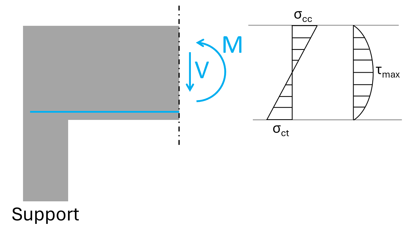
This line load leads to a bending moment and a shear force when we cut the beam close to the supports. The bending moment leads to normal stresses with compression in the top and tension in the bottom, while the shear force V leads to a shear stress distribution which is 0 at the outermost fibres and has its maximum value τmax at the ceontroid of the cross-section.
The shear stress τmax at the centroid is equal to the principal stresses.
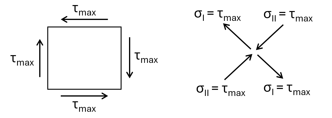
You might have already seen now, why we get the diagonal cracks. The principal tension stresses σI basically pull the concrete apart.
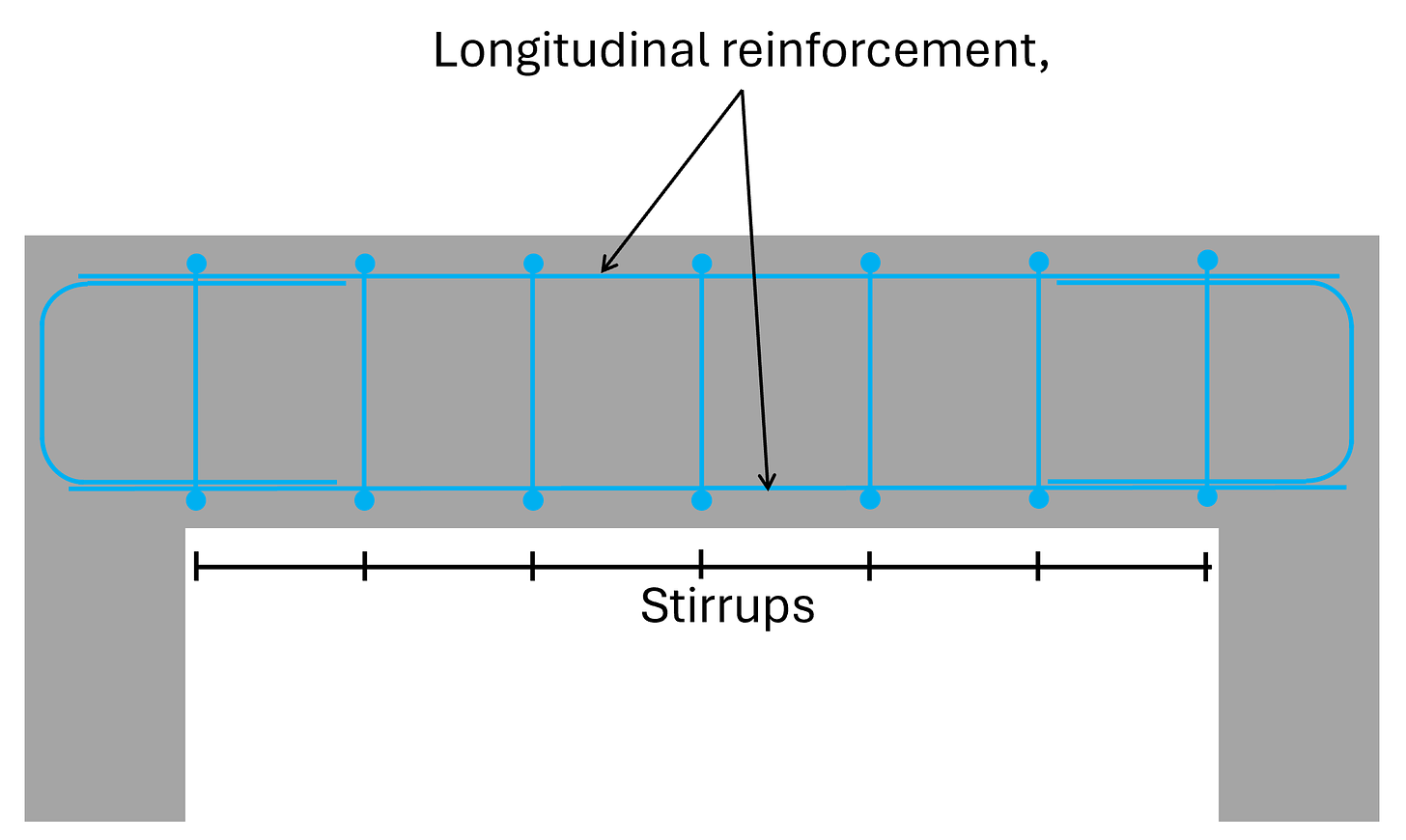
Alright, now to solve this “issue” of diagonal cracking, we add stirrups.
These stirrups basically help “hold the beam together”.
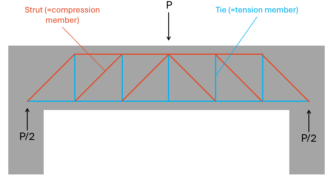
Now, the beam can actually take up tension forces vertically. This means that we can use a strut & tie model / truss model to transfer the vertical loads to the support.
With this strut & tie model, the stirrups have to be designed to resist the vertical tension forces and the concrete needs to be checked for the compression forces of the struts.
Hope this explanation helped understand shear a bit more. Writing this, I researched a lot and learned a bunch myself. In structural engineering, there is always more to know.
Now, let’s check out how we verify shear with shear reinforcement according to Eurocode..
Shear verification with shear reinforcement in 5 steps
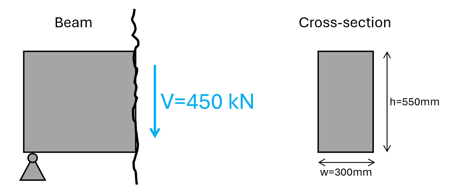
We’ll use the same beam cross-section as in our bending and shear verification without shear reinforcement tutorials. The shear force we’ll use is 450 kN.
Shear with reinforcement is verified with EN 1992-1-1 6.2.2.
There are different approaches to the steps, we do in the following. We are going to verify the diameter of the stirrups. But you can also choose to verify shear capacity. This is up to you.
Step #1: Define the properties of concrete and reinforcement
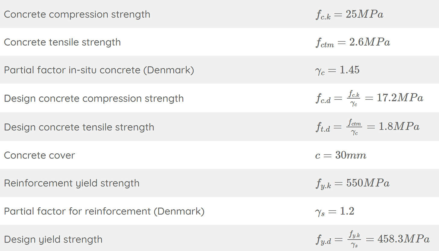
Here are the concrete and reinforcement properties, we use in this tutorial.
Step #2: Lever arm and cross-sectional area of the shear & longitudinal reinforcement
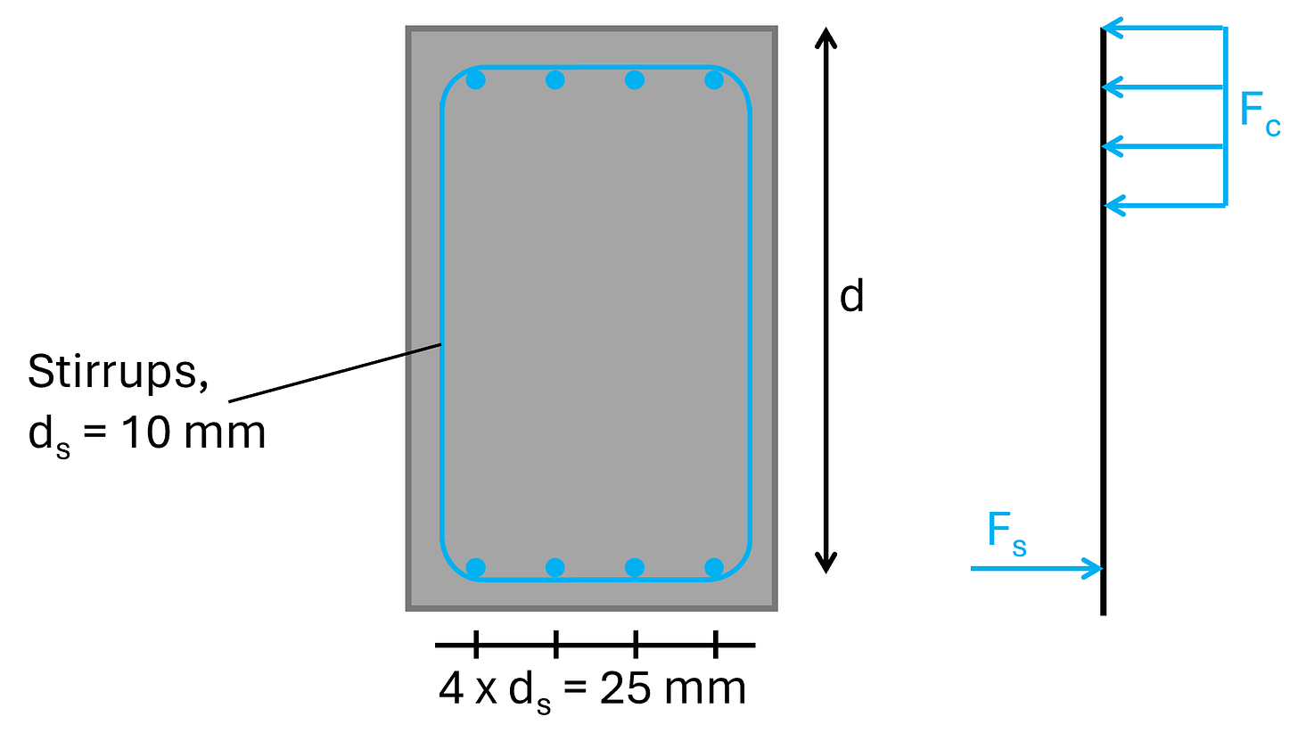
We are repeating stuff here. But I like to repeat things as often as possible. And some of you might have missed the articles from the last 2 weeks. The lever arm or effective height of the longitudinal reinforcement is the distance of the center of the reinforcement to the top or bottom fibre of the cross-section which is in compression.
In our case (with a positive bending moment - simply supported beam) it’s the distance from the bottom longitudinal reinforcement to the top fibre of the section.
For a diameter of the longitudinal reinforcement of ds = 25 mm and the stirrups of dv = 10 mm, then the lever arm is calculated as:
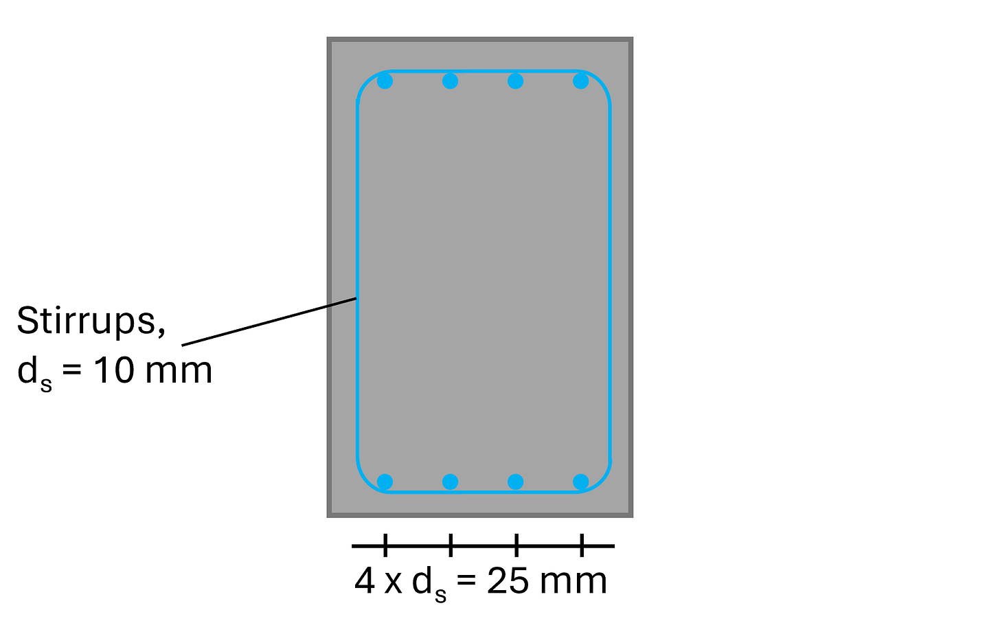
From the picture above, we see that we’ll use 4 longitudinal rebars, which have an area of:
The cross-sectional area of 1 stirrup with a diameter of 10mm with 2 vertical rebars is calculated as:
Step #3: Calculate the design value of the shear resistance with shear reinforcement according to EN 1992-1-1 6.2.2
The design value of the shear resistance for members requiring shear reinforcement is calculated according to EN 1992-1-1 (6.9):
With,
ν1 = 0.6 according to EN 1992-1-1 (6.9) as a strength reduction factor for concrete cracked in shear
αcw = 1.0 as a coefficient taking into account the state of stress in the compression chord
z = 0.9 ⋅ d = 448 mm (EN 1992-1-1 Figure 6.5)
cot(θ) = 2.5 → EN 1992-1-1 (6.7N)
tan(θ) = 0.4 → EN 1992-1-1 (6.7N)
Step #4: Verify that the shear force VEd < the design shear resistance with shear reinforcement VRd.max
A design shear force of 450 kN and a shear resistance of 479 kN lead to a utilization of:
Step #5: Calculate and define the spacing of the shear reinforcement
As a last step, we’ll calculate the spacing of the stirrups.
First, according to EN 1992-1-1 (6.8), we’ll reduce the design yield strength of the reinforcement:
The required cross-sectional area of the shear links is calculated with EN 1992-1-1 (6.8):
The shear reinforcement (=stirrups) is vertical. Therefore, α is set to:
The maximum spacing is calculated with EN 1992-1-1 (9.6N)):
We therefore set the spacing of the spacing of the stirrups to:
→ Required cross-sectional area of the shear reinforcement of 1 stirrup:
The required cross-sectional area of 1 stirrup is therefore (1 stirrup has 2 vertical “rebars”):
And the required bar diameter:
Now, we could reduce the stirrup diameter from 10mm to 8mm, or just leave it to have some extra capacity. In general, I always like to have some extra capacity. It often times saves you (and your design) when design changes come from the architect or if someone forget to tell you that the live load was changed from 1.5 kN/m2 to 3.0 kN/m2.
Final words
This was one of these endless weekends of studying and researching about shear in rc elements. In the end, it took me 10 hours to write. But it was fun and I can say that I understand shear on a deeper level now.
Have a great rest of the week. I’ll see you next Wednesday for part #7 of the reinforced concrete series.
If you missed episodes #1 - #5 of this new series, then you can find all previous posts → here ←.
Thanks for reading today’s episode.
Let’s design better structures together,
Laurin.
P.S. Have you already seen my latest YouTube video about punching shear of reinforced concrete slabs? We’ll cover it in the newsletter in a few weeks, but if you don’t want to wait any longer, then you can check it out → here ←.


