

Reinforced Concrete Column Design
A step-by-step guide

Hi friends, ✌️✌️
We take a break from the Engineering Mechanics series for a week and look at all the calculation steps required to design a reinforced column according to Eurocode.
This will give you an overview of what steps you have to go through if you want to verify a rc column and design its reinforcement. I recommend, you’ll get a copy of Eurocode 2 and go through each formula yourself to see if you get the same results. This can be with a pen, paper and pocket calculator. Or, what I recommend is to use a software tool like Mathcad, SMath or Calcpad.
We are showing all calculation steps for an axially loaded reinforced concrete column with corbels. The corbels are used to support beams which support slabs. It’s a good example, because the loads on the corbels emphasize the effects of eccentricities.

Here are the steps:
Define the static system
Calculation of characteristic loads (dead, live and snow load)
Set up load combinations to calculate design loads
Define properties of concrete and reinforcement
ULS bending and compression verification
Alright, let’s dive into it. 🚀🚀
#1 Static system
The column is only exposed to vertical loads and doesn’t take up lateral loads from wind or earthquakes. The column is furthermore a precast element. Therefore it makes a lot of sense to use the static system of a simply supported beam/column with 1 pin and 1 roller support.

#2 Characteristic loads
We’ll assume in this tutorial that we design the column of a 1-storey building. Now on a 1-storey building, the following loads act:
Dead load of structural and non-structural elements
Live load of the roof
Snow load and
Wind load
We’ll do a lot of assumptions in this tutorial, but if you want to learn more about loads on roofs, you can check out this article.
Load transfer
❗ The following load transfer explanation works if the building is a traditional structure with simply supported beams, columns and slabs.❗
Live, Snow, Wind and dead load (self-weight of roofing) are applied as area loads [kN/m2] on the roof/slab.
By multiplying the area loads (live, snow, wind, dead load) with the spacing of the beams, line loads are calculated. These line load can now be applied to the beams.
The center reaction forces of the beam system is then the characteristic vertical load that is applied to the column.


But as we design a column with corbels, we have to consider the eccentricities and therefore separate the loads on the right and left corbel.
The following characteristic load values are assumptions, and we’ll only look at the dead and live load.
Left corbel:
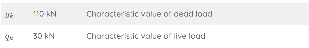
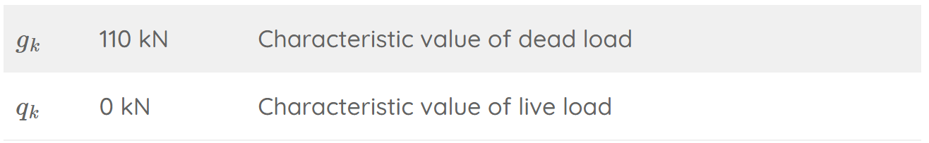
Right corbel:
We’ll design the column for the most critical loading situation, which happens when the live load is set to 0 on one of the spans.
❗❗Be aware that you should also include the dead load of the column. For simplicity reasons, we don’t do that in this tutorial. ❗❗
#3 Load combinations
Load combinations combine the characteristic loads and add safety factors.
→ Detailed guide to load combinations ←
ULS load combinations

SLS Quasi-permanent load combinations
We need the quasi-permanent loads later on to calculate a factor that takes creep into account. We’ll use a psi_2 factor of 0.2 which is the value for offices in Denmark.

#4 Properties of concrete and reinforcement
Material
The concrete and reinforcement will have the following properties:

You can find many of these material parameters on eurocodeapplied.com.
Cross-section
We’ll define the cross-section and beam with the following dimensions:

#5 ULS bending moment verification
💡💡 Quick note: As a structural engineer, I never calculate and verify an RC column step-by-step, as below. Instead, I use software or an Excel spreadsheet. This speeds up the design a lot. However, I recommend going through the calculation at least once to understand all parameters that have an influence on the design.
Bending moment due to eccentricities and imperfections
First, let’s calculate the bending moment due to the eccentricities of the loads on the corbels. We’ll look at the worst case scenario, where we assume that the loads are distributed on the corbel as triangular loads and the smaller load has its resultant closer to the centreline of the column.

Geometry of the column
We’ll define the dimensions of the column with the following dimensions:

Now, we can calculate the eccentricities of Pd.1 and Pd.2.

The bending moment due to these eccentricities is calculated as:

Next, we’ll calculate the bending moment due to imperfections according to EN 1992-1-1 5.2.
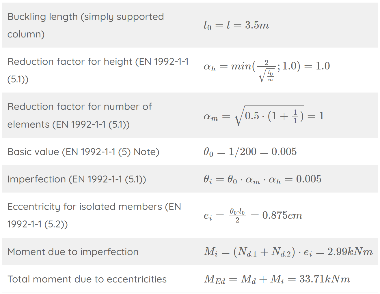
Check if second order effects may be ignored (EN 1992-1-1 5.8.3)

→ Yes, second order effects have to be included.
Method based on nominal curvature (EN 1992-1-1 5.8.8)

Design of reinforcement
We’ll use M-N diagrams to find the required reinforcement to take up the bending moments and normal forces acting in the column.

We’ll use an M-N diagram from Designers’ guide to Eurocode 2: Design of concrete structures (A. W. Beeby et al.) for d1/h = 0.16 and fck < 50 MPa, where we have to calculate the ratios N_d/(w⋅ℎ⋅f_cd) and M_Ed/(w⋅ℎ^2⋅f_cd).

Unfortunately, I can’t insert the M-N diagram, because I am unsure of the copyright. But you basically find the reinforcement ratio where your 2 lines from N_d/(w⋅ℎ⋅f_cd) and M_Ed/(w⋅ℎ^2⋅f_cd) intersect.
From Designers’ guide to Eurocode 2: Design of concrete structures (A. W. Beeby et al.) Fig. 5.8, we’ll find a reinforcement ratio of 0.05 at the intersection point. From this ratio, we can now calculate the reinforcement of the column.

💡💡 11% is a very low utilization ratio. In this case, it would make sense to optimize and decrease the cross-sectional area and the rebar diameter. 💡💡
Conclusion
As a structural engineer, I usually use software or an Excel spreadsheet to calculate all verifications. However, it’s very useful to know how each step works to really get a deeper understanding of concrete as a material.
Also, you need to understand your inputs to get a correct result when using software. And this gets difficult if you don’t know the formulas.
Anyway, hope you liked this week’s email.
Let’s design amazing structures, 🌉🏗️
Laurin. ✌️✌️
Enjoy the newsletter? Please forward to a friend you think could like our structural engineering content. It only takes 14 seconds. Making this one took a few hours. Just forward this link: https://www.structuralbasics.com/newsletter/