RC Beam Design
All Steps You Need To Follow
Hi friends, ✌️✌️
Today, we’ll look at all the calculation steps required to design a reinforced concrete beam according to Eurocode.
This will give you an overview. If you want to dive deeper into the formulas, then check out our step-by-step article. ✍️✍️
Here are the steps:
Calculation of characteristic loads (dead, live, snow and wind load)
Set up load combinations
Define properties of concrete and reinforcement
Calculation of the internal forces
ULS bending verification
ULS shear verification
SLS crack verification
SLS deflection verification
Alright, let’s dive into it. 🚀🚀
#1 Characteristic loads
We’ve written detailed articles about loads, which you can follow to understand how to calculate these loads:
Load transfer
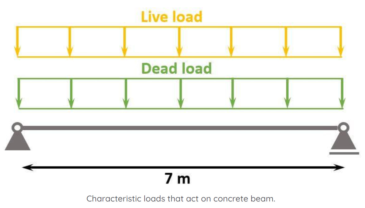
Live and dead load (self-weight of the floor) are applied as area loads [kN/m2] on the floor slabs. The slabs are supported by concrete beams and transfer the loads to these.
By multiplying the area loads (live and dead load) with the spacing of the beams, line loads are calculated. These line load can now be applied to the beams.
We’ll use the following loads:
#2 Load combinations
Load combinations combine the characteristic loads and add safety factors.
→ Detailed guide to load combinations ←
ULS load combinations
SLS quasi-permanent load combination
#3 Properties of concrete and reinforcement
Material
The concrete and reinforcement will have the following properties:
You can find many of these material parameters on eurocodeapplied.com.
Cross-section
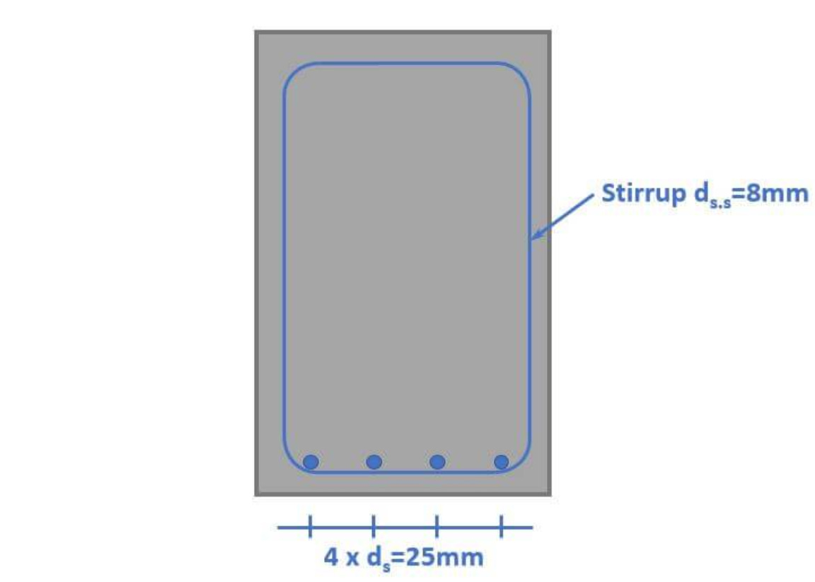
We’ll define the cross-section and beam with the following dimensions:
#4 Calculation of the internal forces
The beam is chosen to be simply supported in this tutorial. For a simply supported beam we’ll find the max. ULS and quasi-permanent bending moment and shear force as:
#5 ULS bending verification
We won’t show every design step in this email. Check out the full article to see the verification more detailed.
We define the diameter of the reinforcement as 25mm.
First, we’ll calculate the lever arm of the reinforcement to the top fibre of the cross-section:
Next, we’ll calculate the required reinforcement:
We check if the minimum reinforcement requires more reinforcement:
We’ll calculate the cross-sectional area of 1 rebar and calculate the required amount of rebars to calculate the reinforcement area:
#6 ULS Shear verification
First, we check if shear reinforcement is required or not.
Members not requiring shear reinforcement
Design value of the shear resistance (EN 1992-1-1 (6.2.a)):
Shear reinforcement is required if the shear force V is greater than V_Rd.c.
Members requiring shear reinforcement
Strength reduction factor for cracked concrete in shear:
Shear resistance (EN 1992-1-1 (6.9)):
Verification is fulfilled if the shear force V is smaller than the shear resistance V_Rd.max.
Shear links (EN 1992-1-1 (6.8)):
Maximum spacing (EN 1992-1-1 (9.6N)):
We choose a spacing and calculate the required cross-sectional area for the stirrup:
Shear reinforcement like stirrups have 2 legs. That’s why we divide by 2.
Required bar diameter:
#7 SLS Crack verification
The crack width limits are found in EN 1992-1-1 Table 7.1N.
1. Calculation of the neutral axis depth of the cracked section
E-modulus of concrete long-term (quasi-permanent):
Long-term steel - concrete ratio:
Equilibrium of the 1. moment of areas:
We solve this equation for x to find the depth of the neutral axis:
2. Calculation of the quasi-permanent moment
We calculate this moment due to the quasi-permanent load.
3. Calculation of the stress in the reinforcement
We calculate the stress in the reinforcement by taking moments at the location of the compressive force.
4. Calculation of the strain
Calculation of the effective height (EN 1992-1-1 7.3.2 (3)):
Calculation of the strain according to EN 1992-1-1 (7.9):
5. Calculation of the max. crack spacing
EN 1992-1-1 (7.11):
Verification
6. Calculation of the crack width
Utilization
#8 SLS deflection verification
The calculation of the deflection of reinforced concrete elements is not as straightforward as for timber or steel structures. However, according to Eurocode EN 1992-1-1 the deflection requirement is likely to be satisfied if the span – effective depth ratio is less than the values given in EN 1992-1-1 Table 7.4N.
For a simply supported beam where the concrete is highly stressed, the limit is 14.
Verification
Conclusion
As a structural engineer, I usually use software or an Excel spreadsheet to calculate all ULS and SLS verifications. However, it’s very useful to know how each step works to really get a deeper understanding of concrete as a material.
Also, you need to understand your inputs to get a correct result when using software. And this gets difficult if you don’t know the formulas.
Anyway, hope you liked this week’s email.
Cheers,
Laurin. ✌️✌️


