


Punching shear explained in 5 steps.
Episode #8 of the reinforced concrete series

Hi friends,
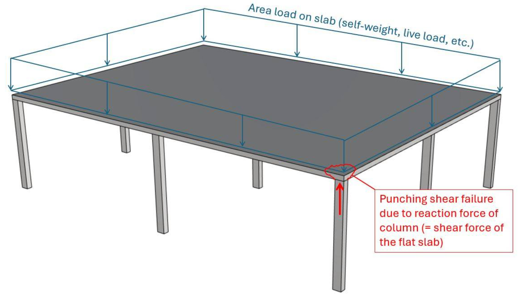
Punching shear is a phenomenon in structural engineering which describes the failure of flat slabs due to concentrated loads, such as columns.
Today, I’ll show you, what punching shear is and how you design and verify flat slabs for punching shear without and with punching reinforcement in 5 steps.
If you prefer video, then you can check out my YouTube tutorial on punching shear design of reinforced concrete slabs (→ click here ←).
If you liked the video, I would really appreciate a like and a subscribe. ✌️
Thanks. Now, let’s get into it.
What Is Punching Shear And Where Does It Happen?
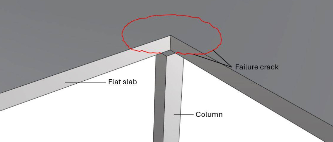
Punching shear is a type of shear failure that occurs close to where a concentrated load is applied to a slab. The failure happens in a circular shape around the concentrated load. The 2 main situations where punching shear occurs are:
flat slabs supported by a column and
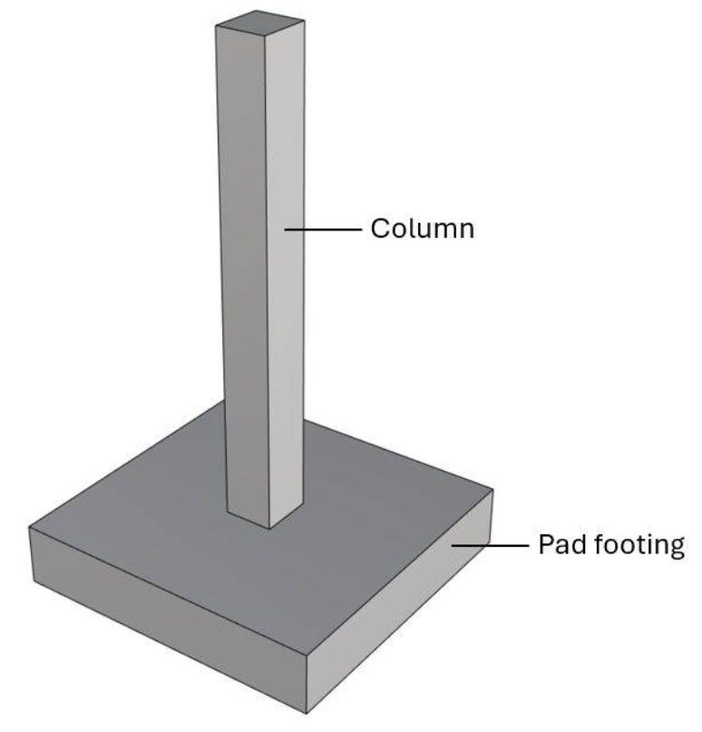
pad footings or foundation rafts that support a column.
The design and verification of punching shear is covered by EN 1992-1-1 6.4.
Punching shear in flat slabs supported by columns
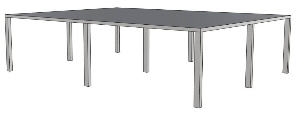
Punching shear has to be verified for flat slabs that are supported by columns, as in the next picture. The most critical will be at the centre column, as this column takes up the most load.
Punching shear in pad footings supporting columns
Punching shear verification without punching shear reinforcement in 5 steps
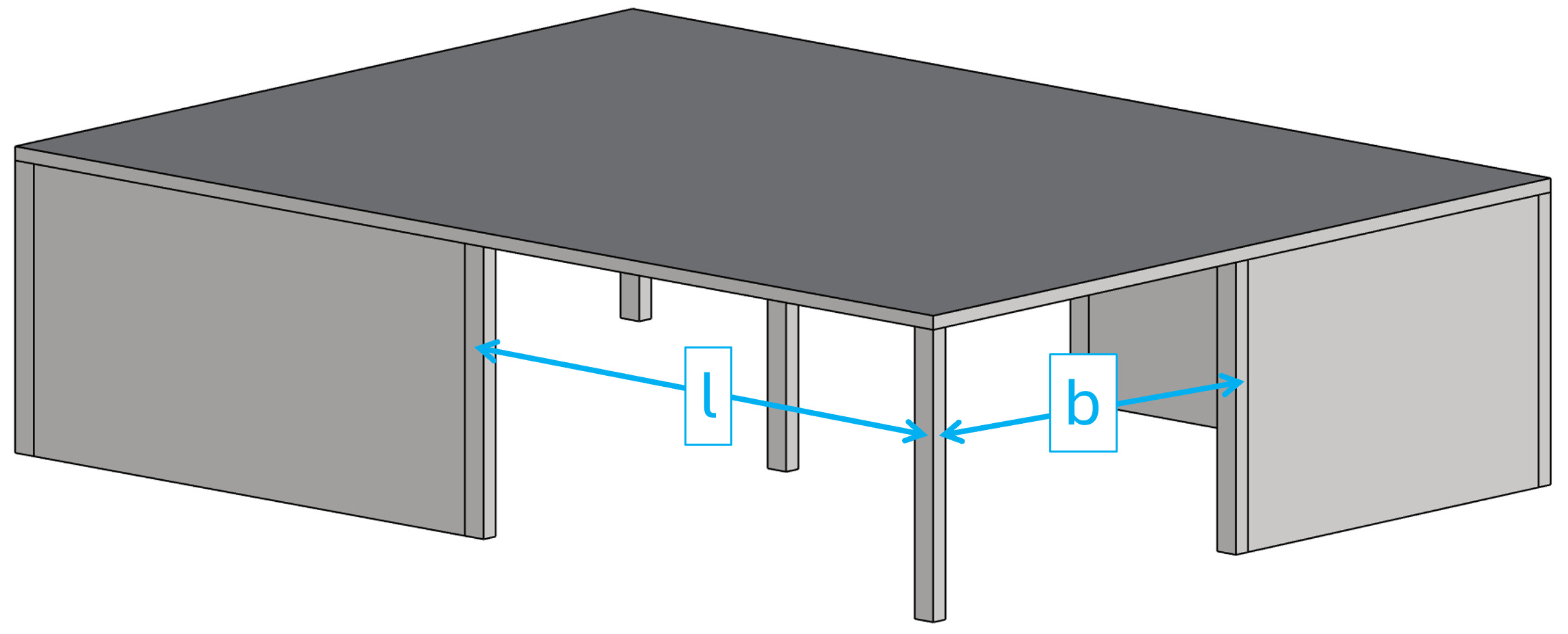
In this article, we’ll explain all calculation steps for the following simplified example, where 9 columns support a reinforced concrete slab. We’ll verify punching shear for the slab above the centre column, because it’s the most critical location of the slab, leading to the highest shear force.
In this tutorial, we first go through the verification steps for punching without punching shear reinforcement and then with punching reinforcement.
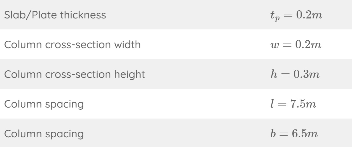
Step #1: Define the geometry properties of the slab and column
The slab and the column have the following geometric properties:
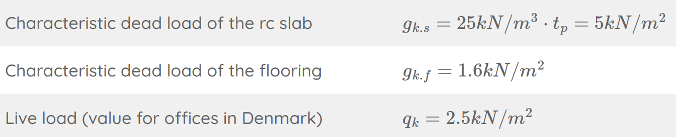
Step #2: Characteristic and design loads acting on the column
In this tutorial, we’ll simplify the calculation of the loads. We assume the slab is exposed to the following area loads:
Load transfer
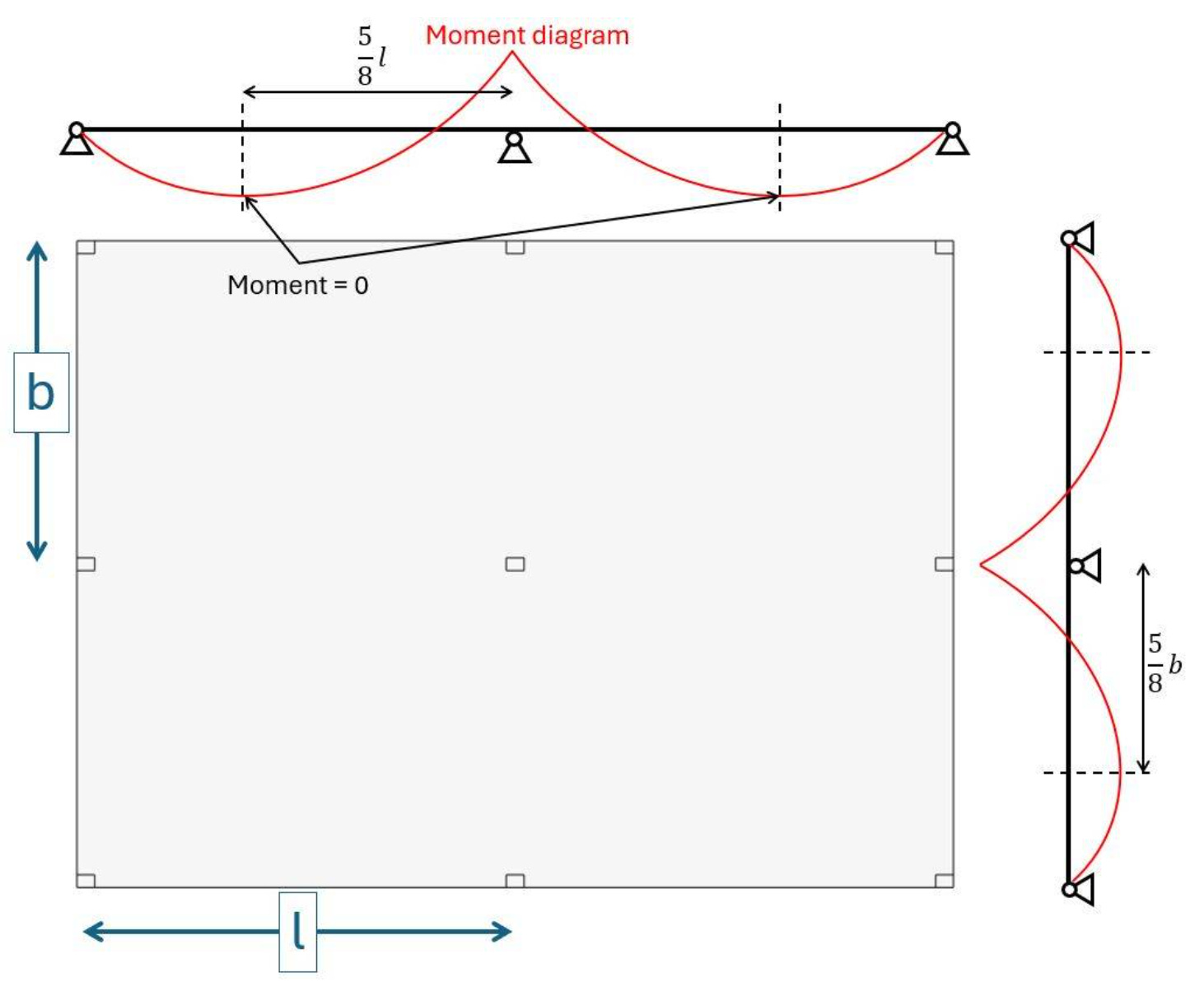
The vertical area loads are taken up by the reinforced concrete slab and transferred to the columns. In regular cases like our example where the column distance is the same, we can use formulas to calculate the reaction forces of the columns (shear force of the slab).
However, the more irregular the supports of the slab are, the better and more accurate it is to use a FE model.
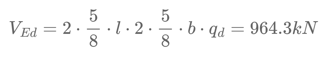
We use the formula of a 2-span continuous beam to find the reaction force of the center column.
With qd as the design area, load on the slab, which we calculate with load combinations.
ULS load combinations

Now, in our case, we only use one load combination, because we simplify this tutorial. Usually, you have to consider multiple load combinations. However, from experience, we can say that for an indoor office slab, this load combination is governing in most situations.
With the design load qd of 12.67 kN/m2, we can now calculate the shear force/ reaction force of the slab at the location of the centre column:
💡INFO💡
If you calculate the shear force of the slab / normal force of the column with a FE model, you won’t get the exact same result. The beams and slabs don’t have exactly the same behaviour, and we used beam formulas to calculate the reaction forces. The stiffness of the slab and columns in the FE model also have an influence of the size of the reaction forces.
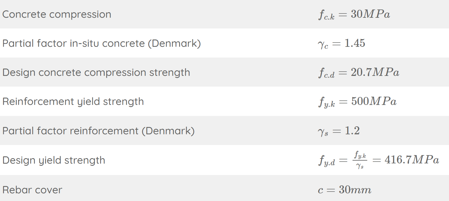
Step #3: Define the concrete and reinforcement properties
Here are the concrete and reinforcement properties we use in this tutorial.
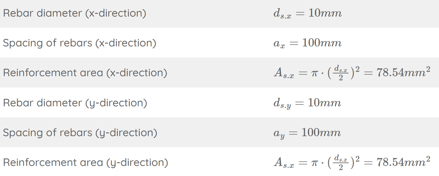
We’ll also assume the longitudinal reinforcement of the slab. Keep in mind that we didn’t calculate that.
Step #4: Punching shear verification without shear reinforcement
The following checks have to be carried out according to EN 1992-1-1 6.4.3 (2):
At the perimeter of the loaded area (column perimeter) the maximum shear resistance stress should not be exceeded:
\(\tau_{Ed} = \tau_{Rd.max}\)Punching reinforcement is not required if the shear stress does not exceed the punching shear resistance without punching reinforcement along the control section:
\(\tau_{Ed} = \tau_{Rd.c}\)If τEd > τRd.c punching reinforcement must be added and verified.
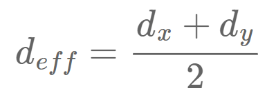
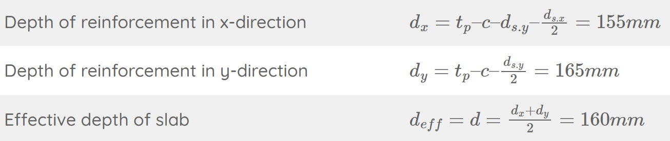
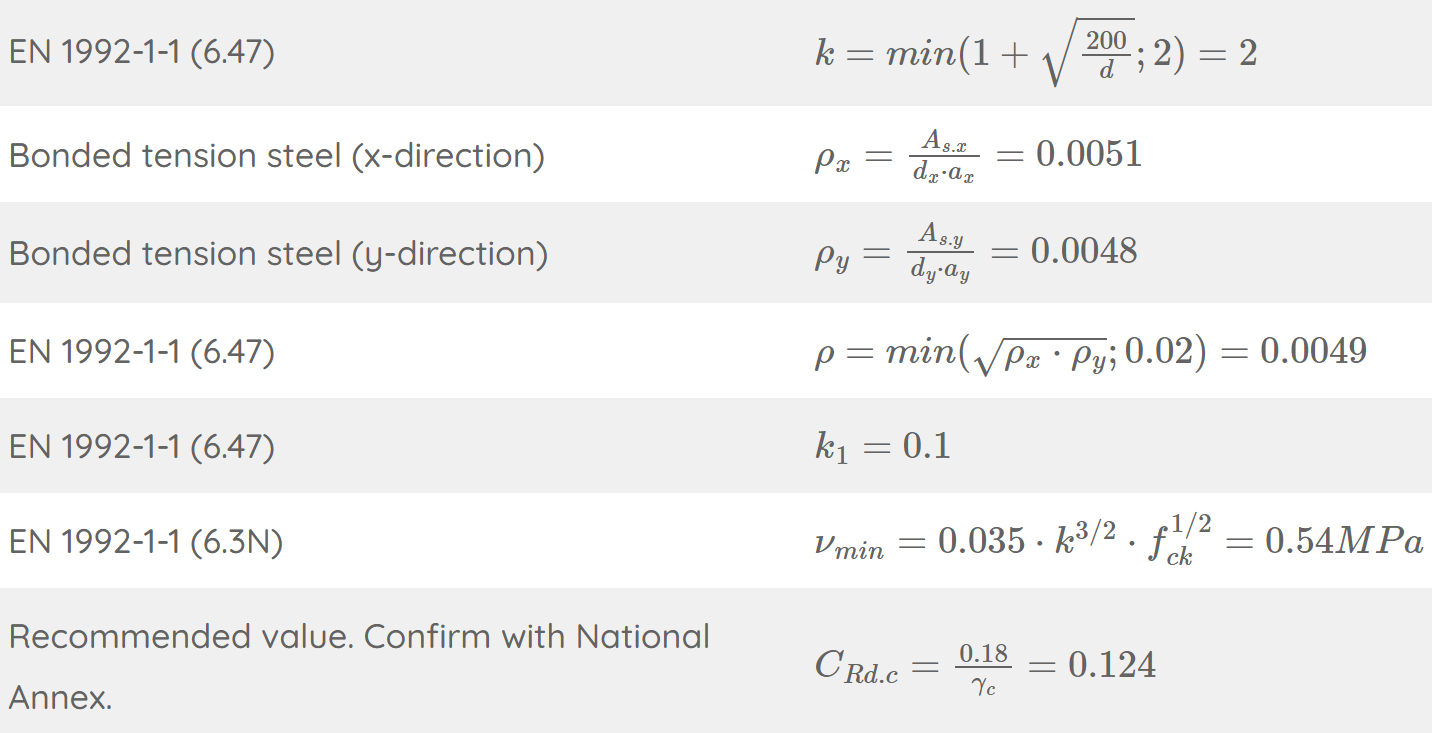
We start by calculating the effective depth of the longitudinal reinforcement by finding the depths of the reinforcement in x- and y- direction.

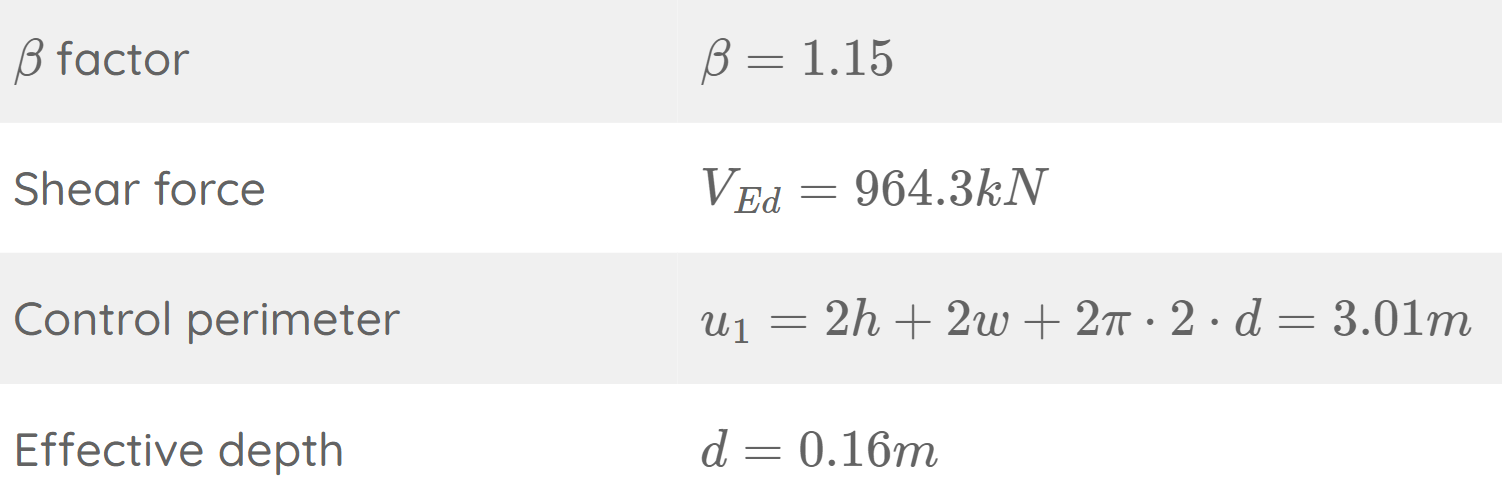
Next, the shear force/stress of the slab can be reduced with a factor β. This β factor is calculated with formulas EN 1992-1-1 (6.39) – (6.46).
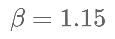
If the columns are not used to stabilize the structure, approximate values for β from EN 1992-1-1 Figure 6.21N can be used. In our structure there are shear walls and therefore the columns are not used as frame action to stabilize the structure.
For the centre column EN 1992-1-1 Figure 6.21N recommends a value of:
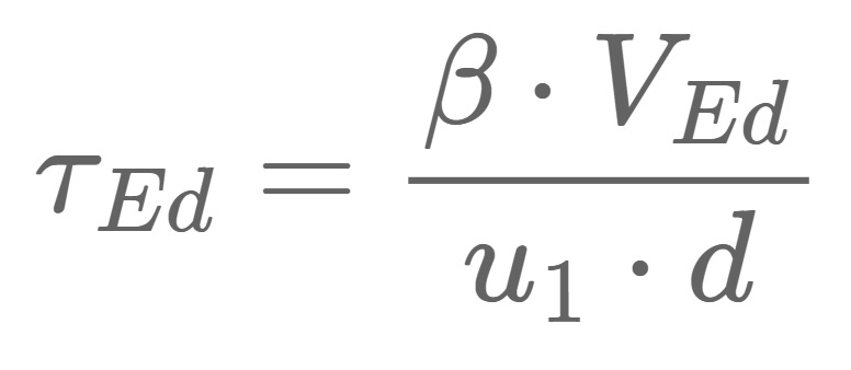
The reduced shear stress is calculated as:
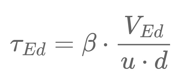
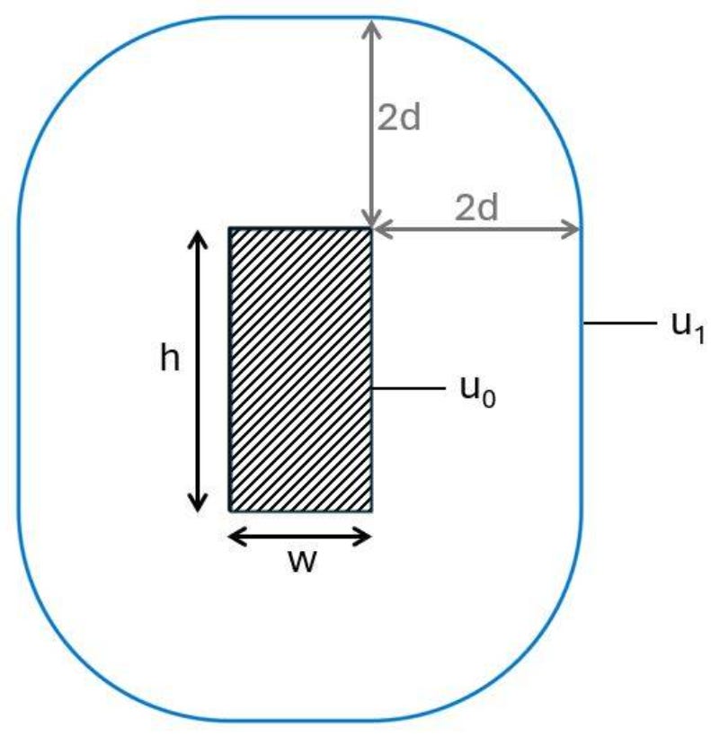
Where u is calculated as the perimeter of the column u0 for verification (1) and the perimeter of the column with a distance of 2d (control perimeter = u1) from all of its edges for verification (2).
Punching shear verification at column perimeter
The first check we’ll do is the verification of punching shear at the column perimeter, using EN 1992-1-1 (6.53):
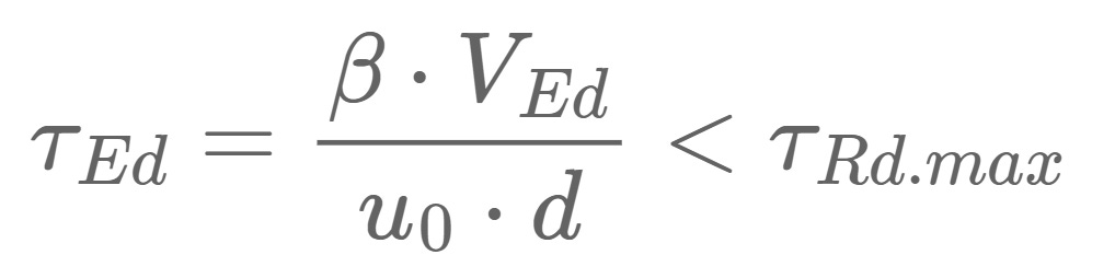
The shear stress is calculated with the following parameters:
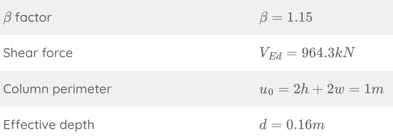
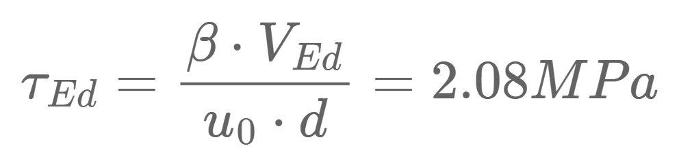
The shear resistance τRd.max is calculated as (EN 1992-1-1 (6.53)):

With,
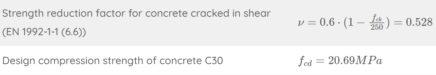
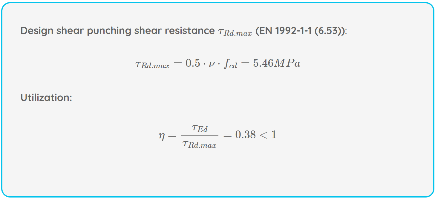
This means that the first check verifies.
Punching Shear Verification Without Shear Reinforcement (EN 1992-1-1 6.4.4)
Next, we’ll check if punching shear reinforcement is required.
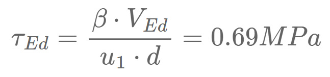
As a first step, we’ll calculate the shear stress at the control perimeter u1:
The shear stress is calculated with the following parameters:
This leads to a shear stress of:
Next, we’ll calculate the punching shear resistance τRd.c:
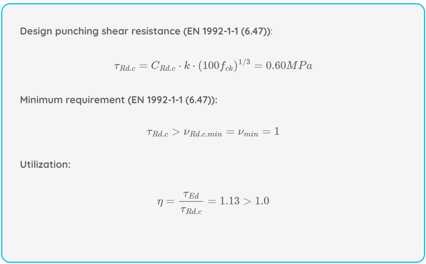
Punching shear without shear reinforcement does not verify, and we will therefore add punching reinforcement and follow EN 1992-1-1 6.4.5.
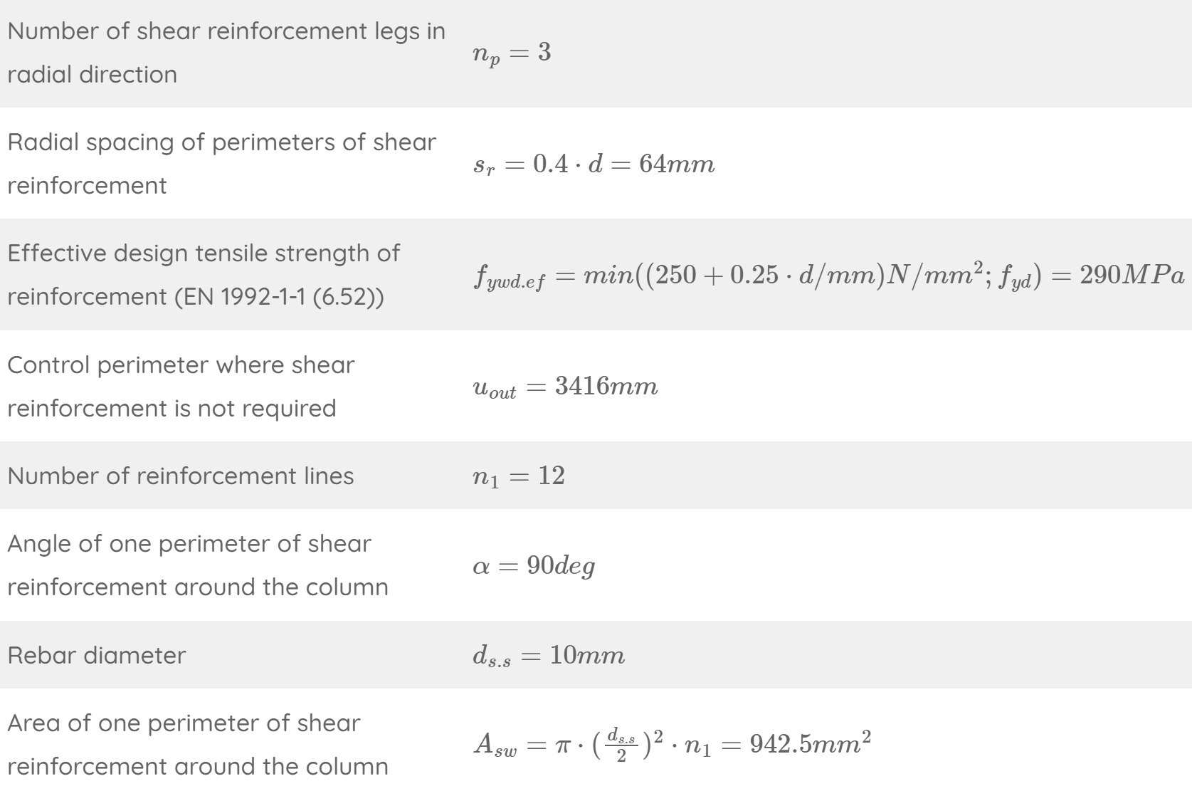
Step #5: Punching Shear Verification With Shear Reinforcement (EN 1992-1-1 6.4.5)
Detailing requirements for punching shear reinforcement are given in EN 1992-1-1 9.4.3.
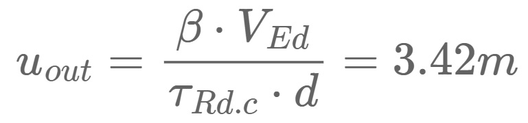
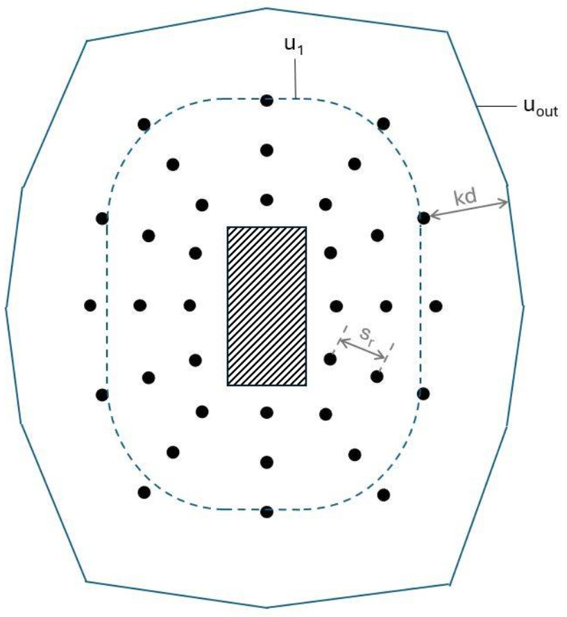
Before detailing the reinforcement, we need to calculate the perimeter uout where no shear reinforcement is required (EN 1992-1-1 (6.54)):
We’ll use the following punching reinforcement layout.

The verification for punching shear with shear reinforcement verifies.
Final Words
This was punching shear. Never forget to verify it. It’s critical in many design situations.
Even in foundation slabs which are supported by pile caps where the support area is really big.
I hope this tutorial helped to understand reinforced concrete better. In module #3 of my book series about the structural design of a residential building, we’ll cover everything more in detail and also use FE software to verify an in-situ concrete slab.
But first, we need to release module #1 Loads on a structural building and module #2 Structural design of the roof structure of a residential building.
Here’s the snippet of the cover.

It’s ready, we are only waiting to launch until Structural Basics is a registered business in Germany. I sent the application already, and I am hoping to get a confirmation soon.
Super excited to share the 1st module with you guys.
If you missed episodes #1 - #7 of the reinforced concrete series, then you can find all previous posts → here ←.
Have a great week and I’ll talk to you next Wednesday.
Thanks for reading today’s episode.
Let’s design better structures together,
Laurin.