Precast Concrete Shear Walls
A Design Guide
Hi friends,
Today, we’ll explain the design steps of precast concrete shear walls.
→ Check out the in-depth article ←
Here in Denmark, where I live and work, almost all new buildings are built in precast concrete. That’s also what I have been designing at work for the past months.
Before we dive deeper into the shear wall design, I want to give you a quick overview of the elements that are commonly used in precast concrete buildings:
Hollow core slabs are used as floor slabs
Pre-tensioned precast or steel beams. These usually have consoles which support the hollow core slabs
Precast concrete columns. These usually also have consoles which support the beams
Precast concrete walls. These are used as shear walls to resist the horizontal loads, but they are also used for the vertical load transfer. Precast concrete walls can also have consoles to support walls and beams.
As always, not all precast buildings are built that way and there are many alternatives.
In this email, we’ll quickly run through the verification steps you have to do to verify precast concrete shear walls. 👇👇
Characteristic loads and load distribution
Load combinations
Define geometry and material properties of the wall
ULS tilting verification
ULS sliding verification
#1 Characteristic loads and load distribution
Now, calculating the loads, the load transfer and distribution are actually its own topics, because there is so much to know about that. In these emails, we try to give an overview of the design steps that need to be taken instead of showing every little detailed design formula. For the detailed designs, check out our blog posts.
Alright, in general, we have to calculate the lateral loads acting on the shear walls such as
Wind load
Seismic load
Imperfections
Earth pressure
And the vertical loads such as
Dead load
Live load
Snow load
Wind load
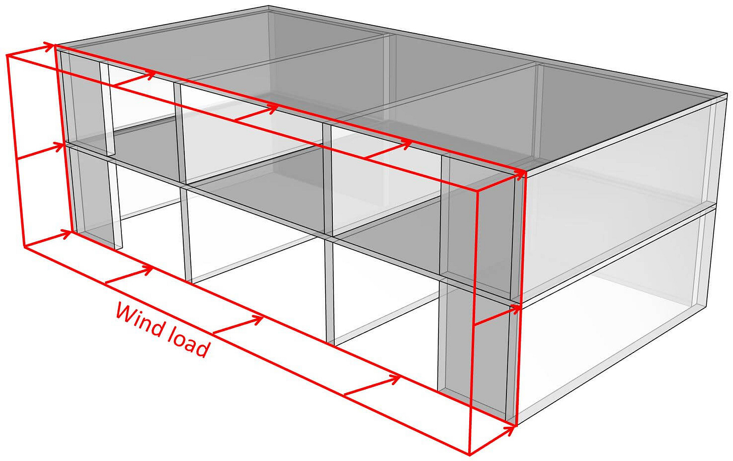
Distribution of the wind load
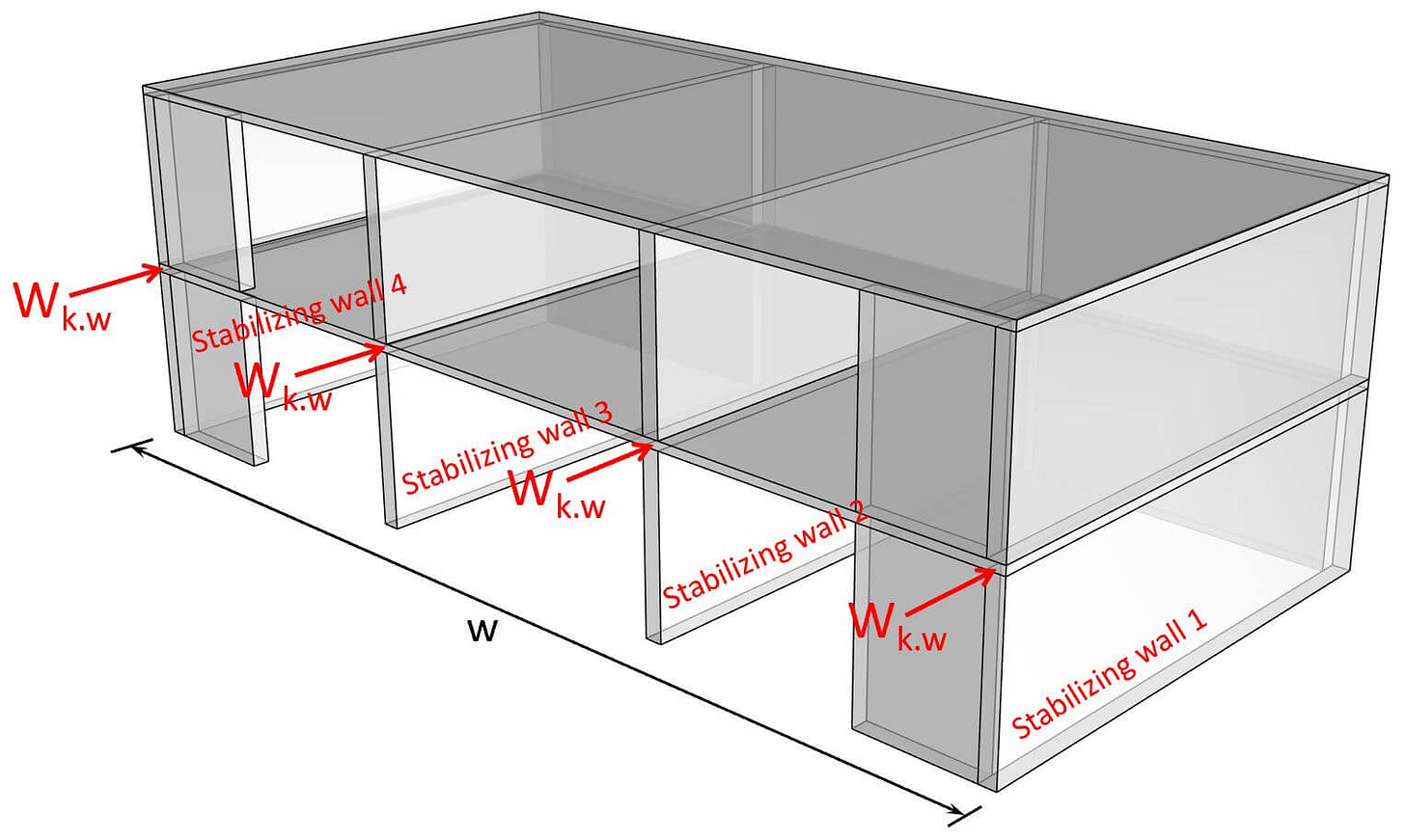
The lateral wind load is first applied to the facade. This load is taken by the floor diaphragms. This means that we transfer the area wind load into a line load and apply it to the floor. Next, this line load somehow has to get down to the foundation and then to the soil. To transfer the line load down to the foundation, we use shear walls. This means that the horizontal wind load travels through the floor slab and to the walls. This load distribution meaning which wall takes how much of the load can be done elastically and plastically. We’ll cover how to do this in another episode.
For now, we’ll assume that each wall takes up 1/4 of the total load.
Step 1
Step 2
Step 3
Vertical loads
Check out the article for more in depth explanations. We’ll define the dead load as: 👇👇
#2 Load combinations
Now, you define all possible load combinations. With some quick calculations and explanations, you might be able to argue why you don’t have to verify the shear walls for a certain load combination. In our case, we’ll define 2 load combinations.
LC1 will be leading for the verification of the shear wall. That’s why, we’ll continue only with LC1. However, LC2 will lead to higher compression stresses at the bottom of the walls. So to verify the joint, you should also consider LC2.
Design load LC1
#3 Geometry of the walls
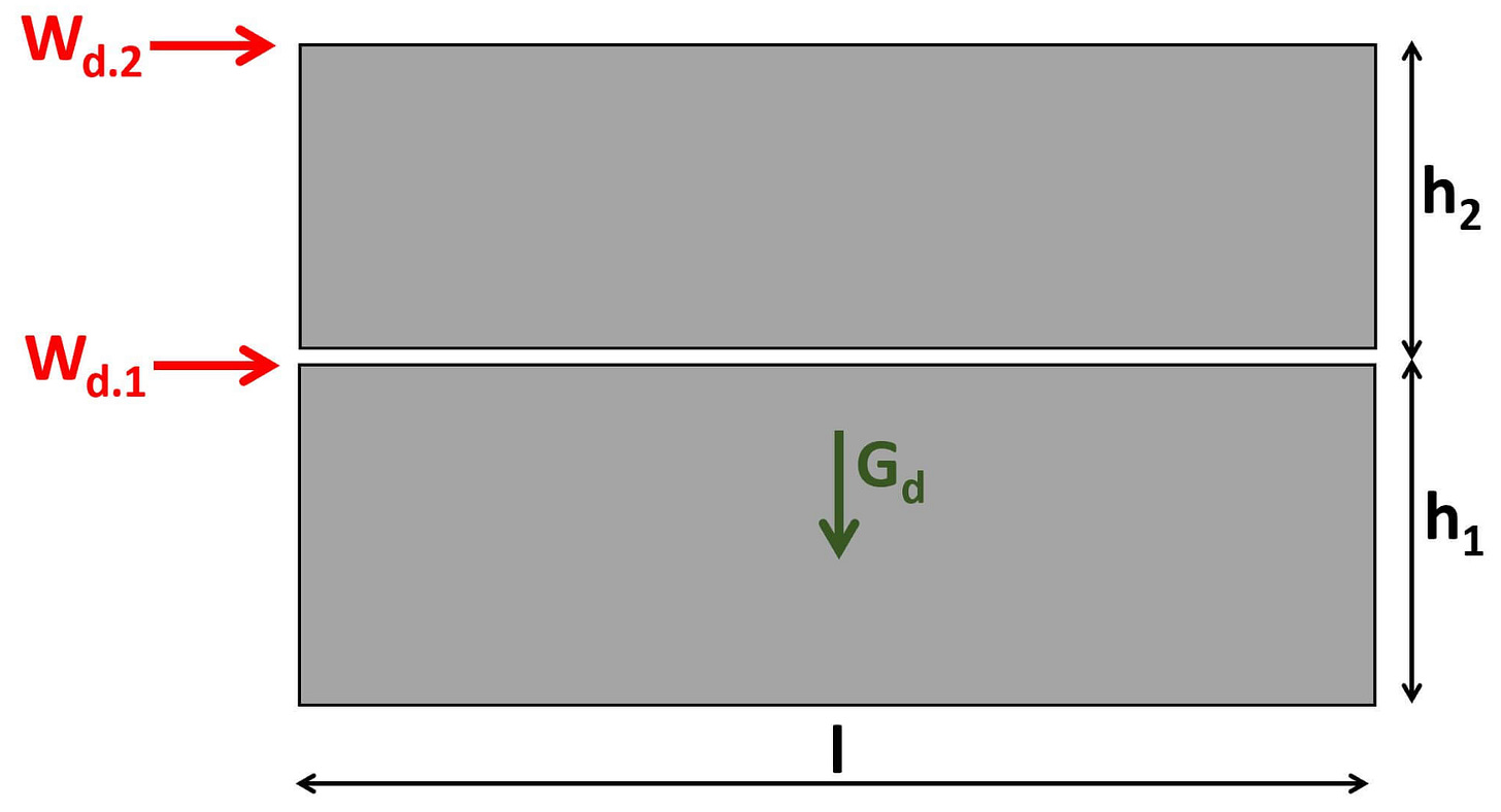
Height of the walls:
The length of the walls is set to 5m.
#4 ULS design - Tilting: Is vertical reinforcement required?
As a first step, we’ll check if the wall is stable without vertical reinforcement. The reinforcement would anchor the wall to the wall below or the foundation.
As both checks verify, we don’t have to add vertical reinforcement.
#4 ULS design - Tilting: Vertical reinforcement required
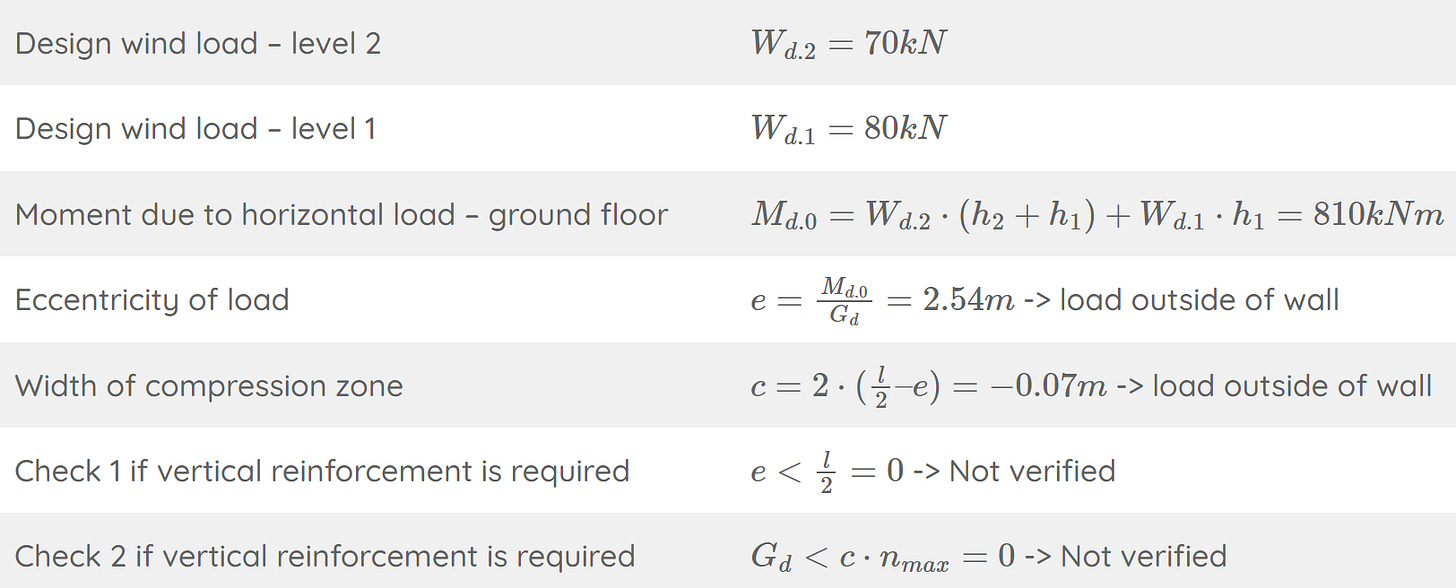
Now, let’s assume we need vertical reinforcement. For that, we increase the horizontal loads and run the calculation again.
Both requirements are not fulfilled. Therefore, we need vertical reinforcement.
Here are some details of how the rebar anchorage looks like.
Calculation of the tension force:
Lastly, we’ll verify the reinforcement required to resist this tension force.
In this case, a rebar diameter of 10 mm is enough. However, a diameter of 25 mm is usually used.
#5 ULS design - Sliding
From my experience, sliding is usually not the critical verification.
Sliding sometimes becomes the critical verification for very long walls, which are exposed to high horizontal loads and small vertical loads.
For sliding, we check that the shear force at the element base is smaller than the shear resistance of the joint.
I might publish a few more articles on the blog about precast concrete design in the new year. But let me know in the comments if you are interested in that. ✍️✍️
Hope you learned something new.
See you next week for another structural engineering episode.
Cheers,
Laurin ✌️✌️


