

Moment of Inertia
💡 One of the most used geometrical properties in structural engineering

Hi friends, 👋👋
Moment of inertias are used in for many structural calculations. It depends on the shape and dimensions of a cross-section. And calculating the moment of inertia can be a bit tricky if the cross-section is irregular.

So, today we’ll cover:
First, what a moment of inertia is
How to calculate the moment of inertia
Links to formulas for different cross-sections
Bonus tip: Quick calculation of the moment of inertia of complex cross-sections
So let’s get into it. 🚀🚀
What Is The Moment Of Inertia?
The moment of inertia is an important parameter used in the analysis and design of beams and other structural elements which are subjected to bending↩️. It is a measure of an object’s resistance to changes in rotational motion, and we use it in structural design to calculate the bending stresses that a structural element will experience when subjected to a bending moment.
It’s a measure of how the material of a structural element is distributed with respect to the axis of rotation, like, for example, the centreline of a beam.
The greater the moment of inertia, the greater the bending resistance of a structural element. So the greater the moment of inertia, the more load a beam can resist.
Before we look at the calculation of the moment of inertia, we have to clarify some concepts.
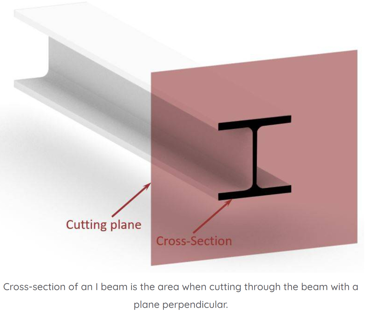
The moment of inertia is calculated by cross-sectional dimensions (height, width, etc.). In structural engineering, cross-sections are determined by cutting through a 3D structural object, like a beam, column, slab, etc. perpendicular to its length. This is visualized in the following picture, where the cross-section of an I or H beam is shown.
Some examples of where the moment of inertia is used in structural design/verification are:
Bending verification of timber beams (link to design guide)
Deflection calculation of timber beams (same link as bending verification)
Buckling verification (link to design guide)
Calculation Of The Moment Of Inertia
Alright, so there are very “theoretical and difficult” formulas to calculate the moment of inertia calculated with integrals and easier formulas which are derived from the “difficult” formulas. (I never liked the difficult formulas😉😉). But it does help a lot to know where the “easier” formulas come from.
Please don’t run away – those formulas scared me as well when I saw them at university. We will try to make it as practical as possible and bridge the gap to the formulas we are actually using as engineers.
But for everyone who doesn’t understand the following derivation or wants the shortcut: Scroll down to the parallel-axes theorem. ⬇️⬇️
Ready? So, the following expressions are the general formulas for the moment of inertia around the two main axes x and y used in structural engineering.


From this expression, we can actually calculate the formula of the moment of inertia of the rectangular cross-section shown in the picture above.
Now, when calculating 𝐼𝑦, dA can also be written as 𝑤 𝑑𝑧 as the limits of the inner integral are from 0 to w.

Let’s integrate further to get to the formula of the moment of inertia of a rectangle.

Voilà, this is the moment of inertia formula for the strong axis of a rectangular cross-section.
We could do the same now for the weak axis 𝐼𝑧 as well.
But let’s rather get to the general and “easier” formula for calculating the moment of inertia: It’s called the parallel-axes theorem.
Parallel-axes theorem


Let’s apply the parallel-axes theorem on the same rectangular cross-section again to see that we’ll get the same formula.

So, we basically got the same formula as before with the integral calculation. 🎉🎉
Now, let’s insert some values in the formula.
Width w = 100 mm
Height h = 240 mm
This results in a moment of inertia of the strong axis of: 👇👇

However, this was only one example of the moment of inertia of 1 cross-section. Let’s have a look at what other sections exist. ⬇️⬇️
Moment Of Inertia Formulas Of Different Cross-Sections
Here’s an overview of the moment of inertia formulas for strong and weak axis for 8 of the most commonly used cross-sections.

And here’s the link to the article with calculation examples.
Bonus Tip: Quick Calculation Of The Moment Of Inertia Of Complex Cross-Sections
In engineering, you sometimes come across complex cross-sections, like in the picture below. In a university course, I had to calculate the moment of inertia of that section. It was a beam used on the edge of a deck cross-section of a cable-stayed bridge.

To be honest with you – who likes to calculate the moment of inertia of such a profile?
It’s time-consuming and prone to errors.❌❌ I’d rather spend my time designing structural elements. But luckily, there is a great tool that can help us to calculate the area.
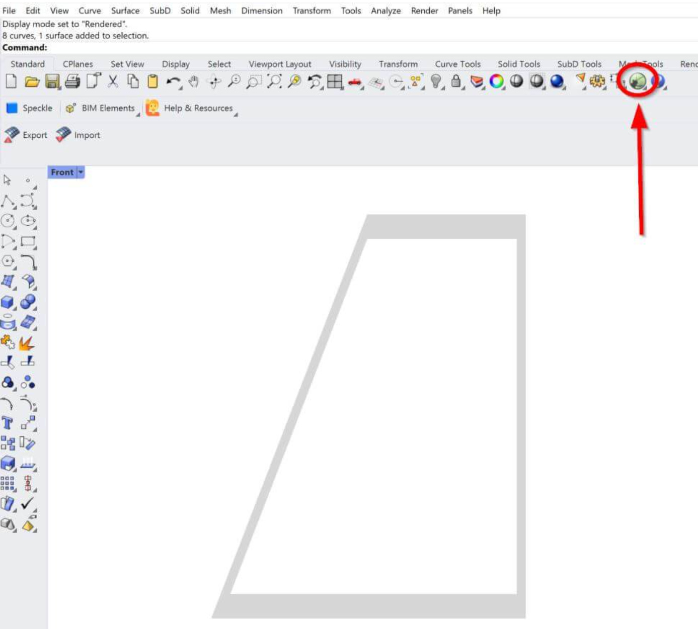
→ It’s Rhinoceros/Grasshopper ←
1. We simply draw the geometry in Rhinoceros and create a surface from lines.

2. We then open Grasshopper.
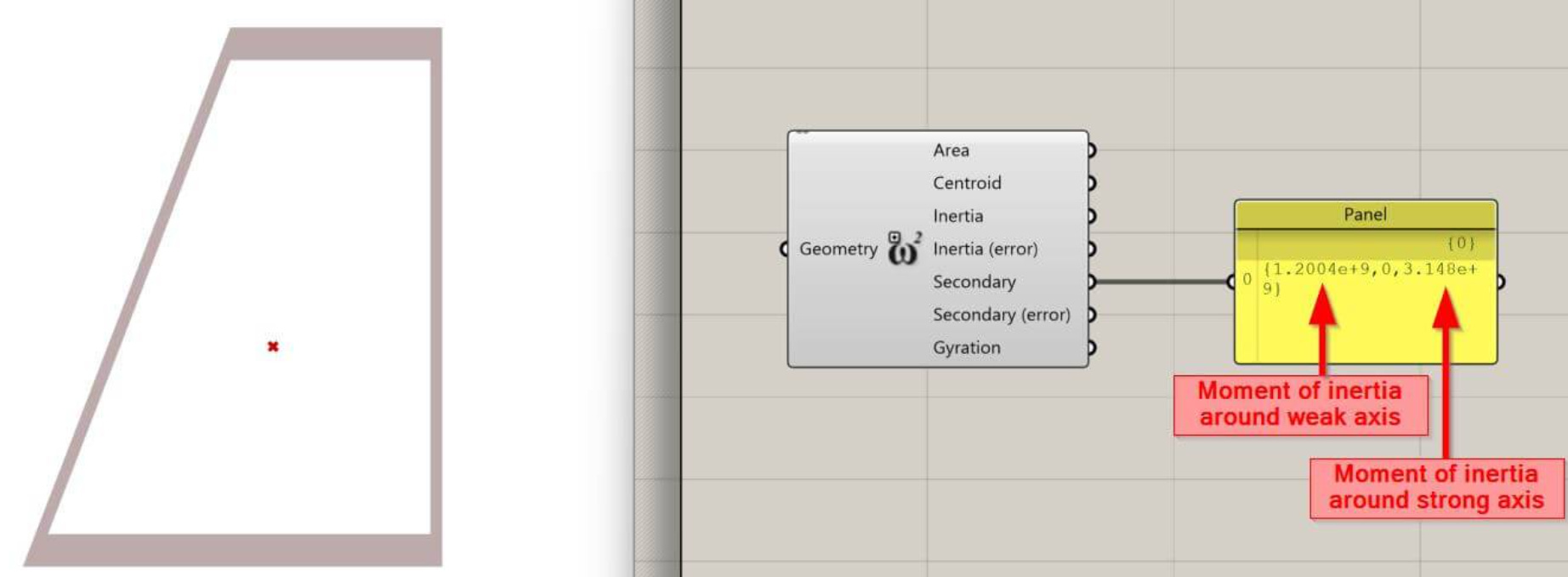
3. In Grasshopper, we click on Surface, Analysis and Area Moments.

4. Right click on Geometry of the component, click on Set one Geometry and select the surface of the Cross-section.

5. Last thing we need to do: Connect a panel with the output of the Area Moments component to see the result.

Now, we just connect the area output with the panel input, and we can see the calculated Moment of inertia. Be careful here❗, because the third value is the moment of inertia around the strong axis, while the first value is around the weak axis.
💡And the unit of the results is what you selected when Rhino was opened.
Conclusion
We are getting closer to the end of the engineering mechanics series. Is that a thumbs-up 👍 or a thumbs-down👎?
Next week, we’ll look at what the section modulus is and how we calculate it. Spoiler alert: it’s quite similar to the moment of inertia.
See you next Wednesday for another episode. 🚀🚀
Have a great rest of the week and a fantastic weekend. ✌️✌️
Cheers,
Laurin.
Enjoy the newsletter? Please forward to a friend you think could like our structural engineering content. It only takes 14 seconds. Making this one took a few hours. Just forward this link: https://www.structuralbasics.com/newsletter/