

How Do Arches Work?
Post #9 of the Engineering Mechanics Series

Hello friends, 👋👋
So far, we’ve explained the following static systems in detail:
Simply supported beam
Cantilever beam
Trusses
You can find all previous posts → here ←
Today we’ll talk about the next structural system - arches.

Here’s what we’ll cover:
What is an arch?
Different static systems of arches
Examples structures of arches
Loading situations of arch structures
Example hand calculation of internal forces
So let’s get into it. 🚀🚀
What is an arch?
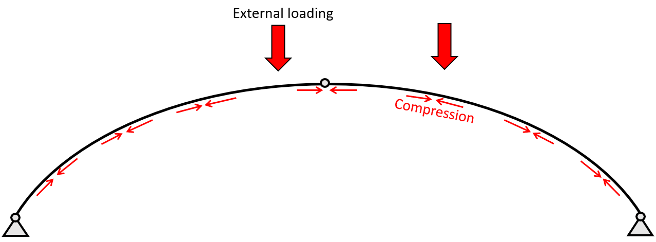
The arch is – statically speaking – a structure that acts mainly in compression, which makes it very efficient. However, the flatter – meaning the smaller the rise to span ratio – the more bending moments it takes. The static system of the arch can have different support conditions, which are explained further in the following.
The static system of an arch
The arch structure has a variety of different static systems due to different support and connection conditions.
The arch is a beam element and can therefore take normal and shear forces, as well as bending moments. Here are the static systems you can choose from: 👇👇
1. Hingeless arch

The hingeless arch is categorized by having 2 fixed supports and no hinged connection. Therefore, the static system is indeterminate. The fixed supports (a) and (b) take up
a vertical reaction force V
a horizontal reaction force H and
a moment reaction M
2. 1 Hinged arch

The 1 hinged arch is characterized by having 2 fixed supports and 1 hinged connection. The static system is indeterminate.
As the hingeless arch, the fixed supports (a) and (b) of the 1 hinged arch take up
a vertical reaction force V
a horizontal reaction force H and
a moment reaction M
3. 2 Hinged arch

The 2 hinged arch is still statically indeterminate and characterized by having 2 pin supports and no hinged connection. The pin supports (a) and (b) of the 2 hinged arch take up
a vertical reaction force V and
a horizontal reaction force H
4. 3 Hinged arch

The 3 hinged arch is statically determinate and characterized by having 2 pin supports and 1 hinged connection.
Due to its statical determinacy, we can calculate the internal and reaction forces due to equilibrium conditions. The pin supports (a) and (b) of the 3 Hinged arch take up
a vertical reaction force V and
a horizontal reaction force H
Examples structures of arches
Understanding the static system of a structure is probably one of the hardest parts about statics and structural engineering in the beginning. At least that was the case for me in early semesters.
From my experience it’s also not that often explained at university and there is very little information about it online as well, isn’t it?
That’s why we are always trying to include some real-world examples in our posts.
1. Supporting structure of bench panels

I saw this bench while being on a walk. I don’t know about you but learning about structures makes me see only structures and static systems when being out on walks. 😀😀 Are you the same? Anyway, I interpret this supporting structure as a 2 hinged arch because it seems to have some rotational capacity at the supports. But keep in mind that different designers might interpret it differently.
2. Supporting structure of a table tennis table
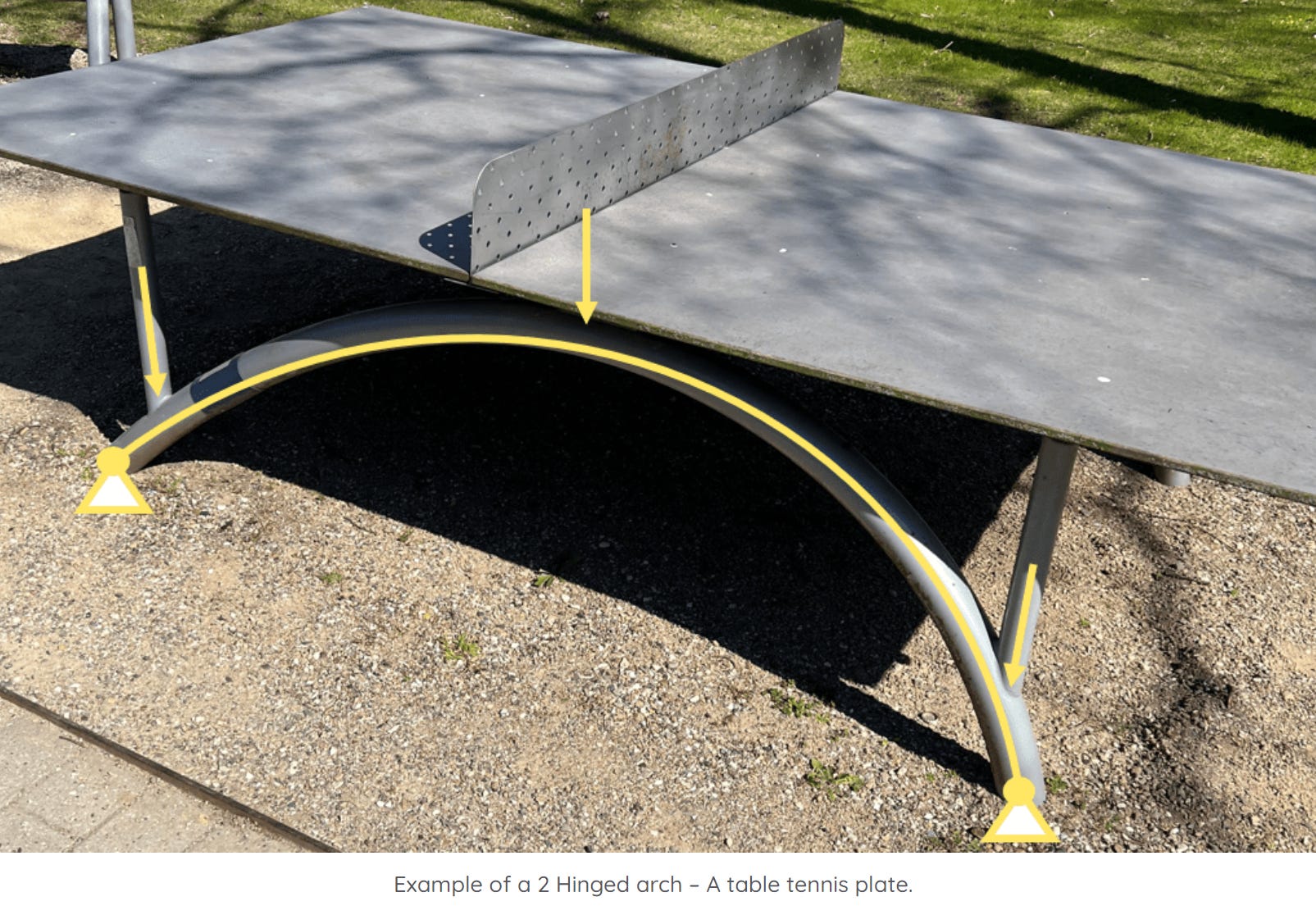
On the same walk, I discovered another 2 hinged arch. It can also easily be seen that all the dead load and other loads of the top plate are transferred as point loads to the arch.
3. Masonry arches

Masonry arches are used to span over windows, doors or other openings. In the picture above, we see that the arch is used to transfer the weight of the wall above and other loads coming from the roof to the columns. I assume that the structural engineer used the static system of a 3 hinged arch, because the building seems to be a few decades old, and the structural engineer might not have had access to advance software at the time. I personally would use a 2 hinged arch these days and use a FE software to calculate the internal forces.
Examples of loading situations
There are 2 very common loading situations, a point load and a line load.
Self-weight of a wall on a masonry arch - Line load

For the case of the masonry wall from the picture above, the self-weight per m is calculated as:
Density ⋅ Cross-sectional Area A
The density of masonry is found by googling (=2000kg/m3). The cross-sectional area of the wall is then calculated as
Height ℎ ⋅ Thickness t = 1.5 m ⋅ 0.4 m = 0.6 m2
which leads to a line load of
2000kg/m3 ⋅ 0.6 m 2 = 11.8 kN/m
Now, it always helps to translate kN in non-engineering language. 11.8 kN/m is also, 1223 kg per m.
That’s roughly as much as a car – but per meter❗ So for the case of our masonry arch where we have a span of 2 m the dead load of the wall above is equal to (almost) 2 cars🚗.

Let’s apply this line load (kN/m) to the 3 hinged arch.

💡💡 Note that the dead load distribution has the same shape as the arch.
A person sitting on a table tennis plate - Point load
Let’s look at the example where a person sits and meditates (🧘♂️) on the table tennis plate above one of the columns which is connected to the arch.

Let’s assume that all the weight is transferred through the plate and into the column. And we assume that this person weighs 90 kg.
This weight of 90 kg can directly be translated into 0.883 kN.
Now because the yogi sits in a specific point with his butt, the load is concentrated and therefore the 0.883 kN equals a point load which is transferred through the column. This point load can then be applied to the arch.

Alright, we’ll now calculate the internal forces of a 3 hinged arch due to the point load. For the sake of this tutorial, we use a 2 hinged arch as a 3 hinged arch in order to have a determinate static system which fulfils the equilibrium conditions. Otherwise, we would not be able to calculate internal and reaction forces by hand.
Example hand calculation of internal forces
First, let’s define the dimensions of the arch.
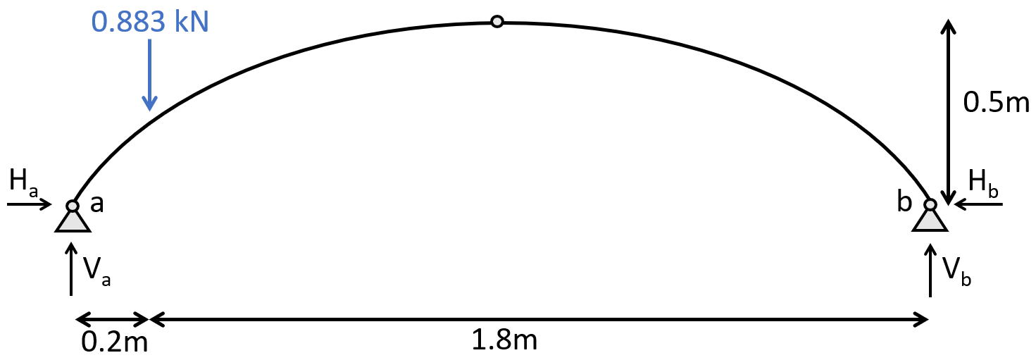
1. The first thing we always calculate for determinate structures are the reaction forces/moment. In our case, that is Va, Ha at support (a) and Vb and Hb at support (b) due to the equilibrium conditions.
Since we don’t have a symmetric loading, we can’t assume that the reaction forces at (a) and (b) are the same. We do therefore moment equilibrium in point (b).

We can now derive Va, since the Moment = 0 in a pin support.
From here, we find Vb from the vertical equilibrium as
To find the horizontal reaction forces, we do moment equilibrium in the top hinge.
We can now derive Ha, since the Moment = 0 is a hinged connection.
From here we find Hb from the horizontal equilibrium as
Failed to render LaTeX expression — no expression found
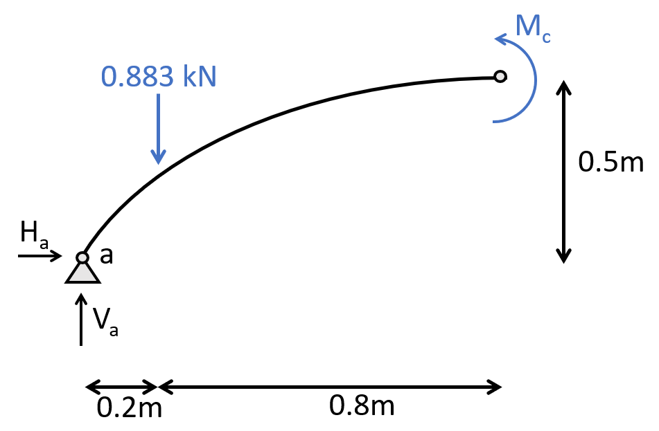
2. Calculation of the shear, normal and moment distribution along the arch due to the reaction forces. The parameter x is introduced as the length between point a and any point on the arch.

There is 2 ways to calculate the length of the arch
by mathematical formulas or
by a CAD program
We choose the second option because it speeds up things a little bit.
3. The shear forces and bending moments can be calculated in dependence of x and the angle alpha, which can be seen in the next picture. Let’s make a first cut at a point between the support (a) and the point load 0 < x < 0.291m. As already mentioned, the dimension 0.291m is calculated in a CAD program.
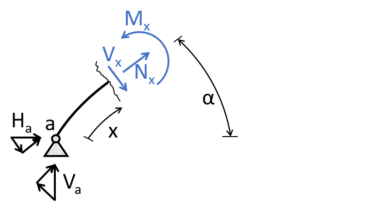
As for the reaction force calculation, the equilibrium conditions are used to calculate the moment and shear forces at point x but this time not in the horizontal or vertical direction but rather in the normal and shear force directions.
This means that we split up the reaction forces in the normal and shear force direction.
For the bending moment calculation it's easier to use the horizontal and vertical distances, which we call x_hor and x_vert.
Let's do a first calculation for one specific point at x = 145mm. From a CAD program we get the other dimensions’ alpha = 49.8°, x_hor = 93.9mm and x_vert = 111mm. The internal forces are now calculated as
💡💡 When the normal force has a negative sign (-) the element acts in compression.
4. Cut at a point between the point load and the hinge connection 0.291m<x<1.159m
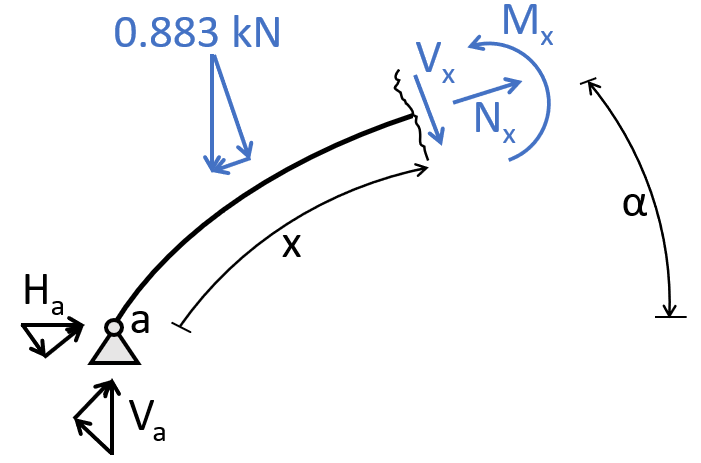
We basically end up with the same equilibrium conditions, except that now the point load is included.
Let's do the calculation for one specific point which has the dimension parameters:
x = 579.5 mm
alpha = 26.59°
x_hor = 441 mm
x_vert = 368 mm
💡💡 We insert that many different points along the arch in the internal force formulas to get many values which we later can use to draw the shear, normal and bending moment diagrams.
5. Cut at a point between the point load and the hinge connection 2318mm < x < 1159mm
This email is already too long. We won’t show the calculation of this point here, but you can check out our blog post, where we calculated the internal forces at more points along the arch.
6. Bending moment, normal force and shear force diagrams
The diagrams can be plotted by a tool like Excel or Grasshopper using the formulas from above or drawn by hand when one is aware of the geometrical shape of the distribution.
Normal force diagram

Shear force diagram

Bending moment diagram

Conclusion
I’ll repeat this over and over again, because it’s important:
Calculating the internal forces over and over and over again for different static systems is key to understanding the process and making less mistakes. If you’ll become a structural engineer, this will also help you understand the results of software programs better and let’s you find mistakes.
The arch was the 4rd example we looked at. Are you curious what comes next Wednesday?
Hope to see you there. 😎😎
This was already the 9th edition of the engineering mechanics series.
Have a great rest of the week. ✌️✌️
Cheers,
Laurin.