

Continuous beams
Post #11 of the Engineering Mechanics Series

Happy Wednesday friends, 👋👋
Today, we’ll cover the last static system in this series: the continuous beam. Finally?

So far, we’ve explained the following static systems in detail:
Simply supported beam
Cantilever beam
Trusses and
Arches
Frames
You can find all previous posts → here ←
Here’s what we’ll cover:
What are continuous beams, and where are they used?
The static system
Examples structures of continuous beams
Formulas for internal forces due to different loading situations
So let’s get into it. 🚀🚀
What is a Continuous Beam?
A continuous beam is a static and structural system that spans over multiple supports (more than 2). This is beneficial for long spans, because the deflection and bending moment are smaller than for simply supported beams with the same load and span.
In most cases, continuous beams are horizontal beams. However, in some cases like 3-span roof rafters, continuous beams can also be inclined.
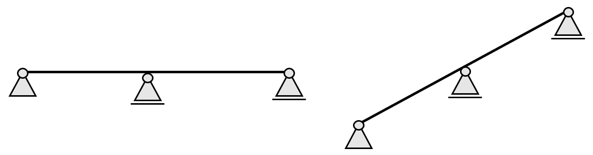
The Static System of a Continuous Beam
The continuous beam has 2+ supports. It could have 3, 4 or 12 supports.
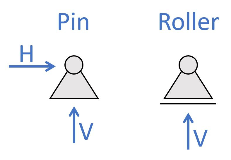
It has 1 pin support and the rest of the supports are roller supports.
1. 2-span continuous beam

The 2-span continuous beam is categorized by having 1 pin and 2 roller supports. The static system is indeterminate, which means we can’t calculate the reaction forces with the 3 equilibrium equations. (We’ll show formulas later in this newsletter.) The pinned support (a) takes up
a vertical reaction force V
a horizontal reaction force H
And the roller supports (b) & (c) take up
a vertical reaction force V
2. 3-span continuous beam

The 3-span continuous beam is categorized by having 1 pin and 3 roller supports. The static system is indeterminate, which means we can’t calculate the reaction forces with the 3 equilibrium equations. (We’ll show formulas later in this newsletter.) The pinned support (a) takes up
a vertical reaction force V
a horizontal reaction force H
And the roller supports (b) & (c) take up
a vertical reaction force V
3. X-span continuous beam
You can add as many supports as you want. There are structures like cable-stayed bridges or foundation beams that have often more than 10 supports.

The x-span continuous beam is categorized by having 1 pin and x roller supports. The static system is also indeterminate, which means we can’t calculate the reaction forces with the 3 equilibrium equations.
For continuous beams with many supports we mostly use FE programs as it’s probably bigger and more complex structures.
The pinned support (a) takes up
a vertical reaction force V
a horizontal reaction force H
And the roller supports (b), (c), (d) & (…) take up
a vertical reaction force V
Example Structures of Continuous Beams
Continuous beams commonly used in structures. One of their benefits is a much smaller deflection as for simply supported beams for the same load and span.
Here are a few real-world examples:
1. Foundation beams supported by pile foundations
Foundation beams are used to support walls, columns and concrete slabs and to distribute those vertical loads to the pile foundations and then to the soil. 👇👇

On the projects, where I have used foundation beams, the spacing of the piles wasn’t the same as the spacing of the columns and walls wasn’t the same either.
Now, you use foundation beams on projects with big loads where strip foundations aren’t enough, and you need to use pile foundations.

2. Cable-stayed bridges
For a very early design, the cables of a cable-stayed bridge can be modelled as rollers and later as spring supports. This makes the bridge deck a continuous beam.

3. Chords of trusses
In the old days, trusses were calculated with hinge connections in every node. We also learn to calculate the normal forces for trusses of that kind in university, because having continuous elements makes the static system statically indeterminate.

However, most trusses have continuous chords, because it’s easier to construct to have fewer connections. And in this case, hinges are precise when the element is actually continuous because bending moments and shear forces are not considered. So, we should model the chords continuous if they are 1 element.

Formulas for internal forces due to different loading situations
You can find the formulas for bending moment and shear forces due to different loading situations on these pages: 👇👇
We’ll now show some example from those pages.
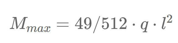
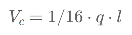
2-span continuous beam - UDL on one span
Max. positive bending moment:
Max. negative bending moment:

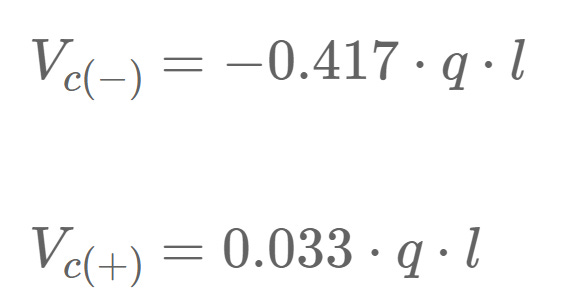
Shear force (at support a):

Shear force (at support b):

Shear force (at support c):
3-span continuous beam - UDL on 2 neighbouring spans

Max. positive bending moment:

Max. negative bending moment (at support b):

Shear force (at support a):

Shear force (at support b):

Shear force (at support c):
Shear force (at support d):

4-span continuous beam - UDL on all 4 spans

Max. positive bending moment:

Max. negative bending moment (at support b & d):

Shear force (at support a & e):

Shear force (at support b & d):

Shear force (at support c):

Conclusion
With the 11th edition of the engineering mechanics series, we have now covered the most important static systems we use in structural engineering.
Tune in next Wednesday to find out what we’ll cover next. See you there. ✌️✌️
Have a great rest of the week.
Cheers,
Laurin.
Enjoy the newsletter? Please forward to a friend you think could like our structural engineering content. It only takes 14 seconds. Making this one took a few hours. Just forward this link: https://www.structuralbasics.com/newsletter/